Electric Power Conversion Device

Active Publication Date: 2017-01-12
TOYOTA JIDOSHA KK
View PDF6 Cites 5 Cited by
  • Summary
  • Abstract
  • Description
  • Claims
  • Application Information

AI Technical Summary

Benefits of technology

[0019]For the short circuit of one of the two switching elements constituting the inverter arm to be detected, it may be detected whether or not the current flowing through the other switching element is excessive with the switching element subjected to the short circuit being turned OFF and the other switching element being turned ON. In this regard, the upper arm short circuit current detection circuitry is used when it is detected whether or not the current flowing through the upper arm switching element is the short circuit current based on the induction voltage generated in the upper arm collector side wiring. The lower arm short circuit current detection circuitry is used when it is detected whether or not the current flowing through the lower arm switching element is the short circuit current based on the induction voltage generated in the lower arm collector side wiring. Likewise, the upper arm short circ

Problems solved by technology

An erroneous detection arises when an external magnetic field is in the Rogowski coil as a noise.
In the Rogowski coil, however, a loop has t

Method used


Image

  • Electric Power Conversion Device
  • Electric Power Conversion Device
  • Electric Power Conversion Device

Examples


Embodiment Construction

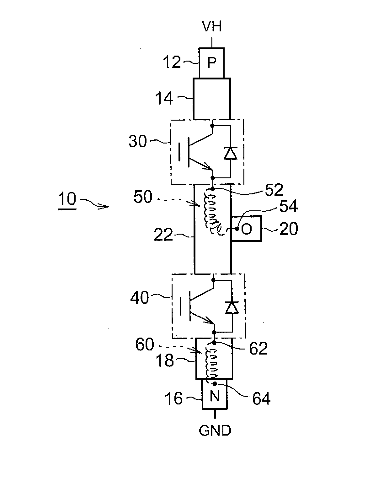
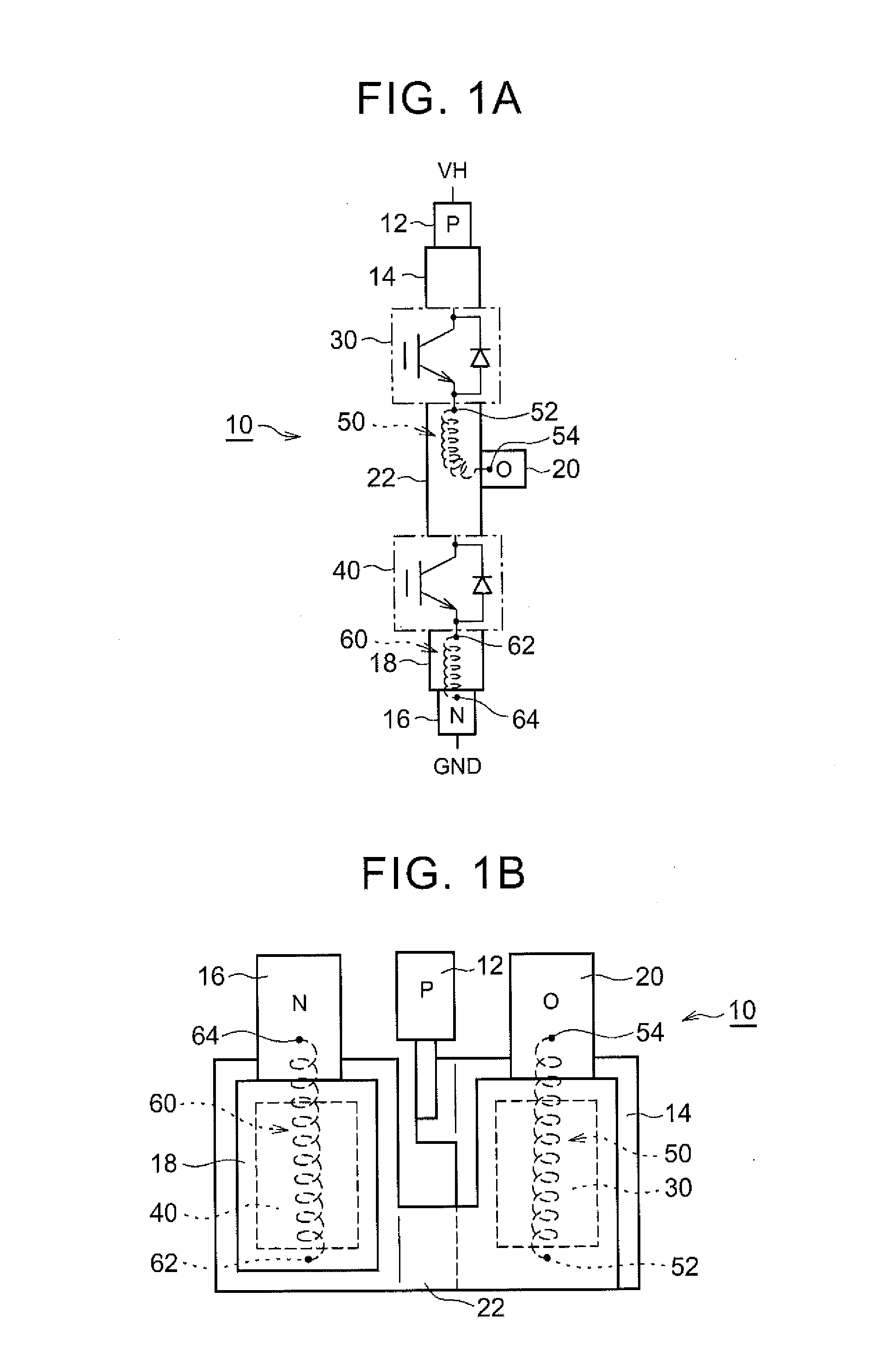
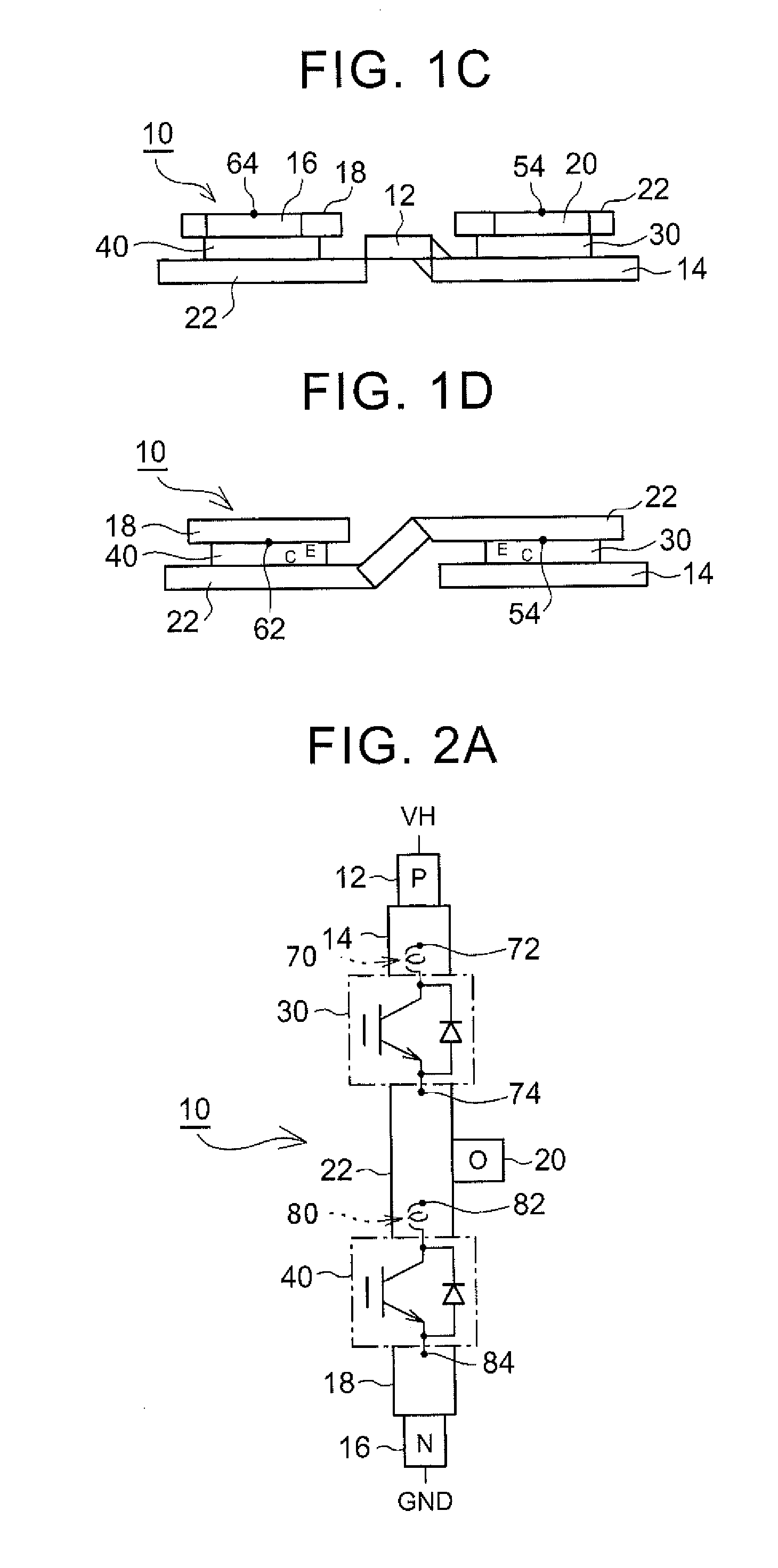
[0043]Hereinafter, an embodiment of the invention will be described in detail with reference to accompanying drawings. In the following description, a single inverter arm will be described as an electric power conversion device. It is an example for descriptive purposes, and the electric power conversion device may be configured to include a plurality of the inverter arms. For example, an electric power conversion device that is configured to include three inverter arms which are connected in parallel can be used in a drive circuit of a three-phase rotating electrical machine.

[0044]The inverter arm is a circuit device in which an upper arm switching element and a lower arm switching element are connected in series between an electric power source and a ground. The potential of the ground is lower than the potential of the electric power source, but it is not limited to 0 V. For example, the potential of the ground may be a negative potential.

[0045]In the following description, an in...


PUM


Abstract

An electric power conversion device includes: a switching element; a collector side wiring connected to a collector side of the switching element; an emitter side wiring connected to an emitter side of the switching element; a detection circuitry configured to detect an induction voltage generated in the collector side wiring or the emitter side wiring when a current flows through the collector side wiring or the emitter side wiring; and a comparison circuitry configured to compare the induction voltage detected by the detection circuitry and a predetermined threshold voltage determined in advance to each other.

Description

INCORPORATION BY REFERENCE[0001]The disclosure of Japanese Patent Application No. 2015-137190 filed on Jul. 8, 2015 including the specification, drawings and abstract is incorporated herein by reference in its entirety.BACKGROUND OF THE INVENTION[0002]1. Field of the Invention[0003]The invention relates to an electric power conversion device and, more particularly, to an electric power conversion device that is capable of performing a detection of whether or not a current flowing through a switching element is a short circuit current.[0004]2. Description of Related Art[0005]It is preferable that a detection of whether or not a current flowing through a switching element is a short circuit current is performed in a quick manner.[0006]As an example, Japanese Patent Application Publication No. 2001-169533 (JP 2001-169533 A) discloses a Rogowski coil being disposed for detection of a current change rate of a main current that flows through the switching element of an electric power conv...

Claims


Application Information

Patent Timeline
IPC IPC(8): H02M7/539H02H7/122
CPCH02H7/1227H02M7/539G01R19/0092H02M1/0009H02M1/08H02M1/32H02M7/5387H03K17/0828H03K17/18
Inventor TOSHIYUKI, KEN
Owner TOYOTA JIDOSHA KK
Why Eureka
Try Eureka