

Reaction method
- Summary
- Abstract
- Description
- Claims
- Application Information
AI Technical Summary
Benefits of technology
Problems solved by technology
Method used
Image

Examples
Embodiment Construction
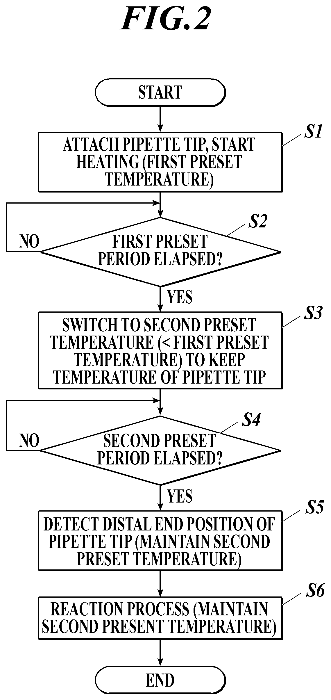
[0036]Hereinafter, an embodiment of the present invention will be described in detail with reference to the accompanying drawings. A reaction method according to an embodiment of the present invention includes a reaction process of supplying and removing a liquid to and from a reaction site multiple times by using a pipette tip for drawing and ejecting a liquid attached to a pipette nozzle, so as to allow two or more substances to cause a reaction.
[0037](Overview of Apparatus Configuration)
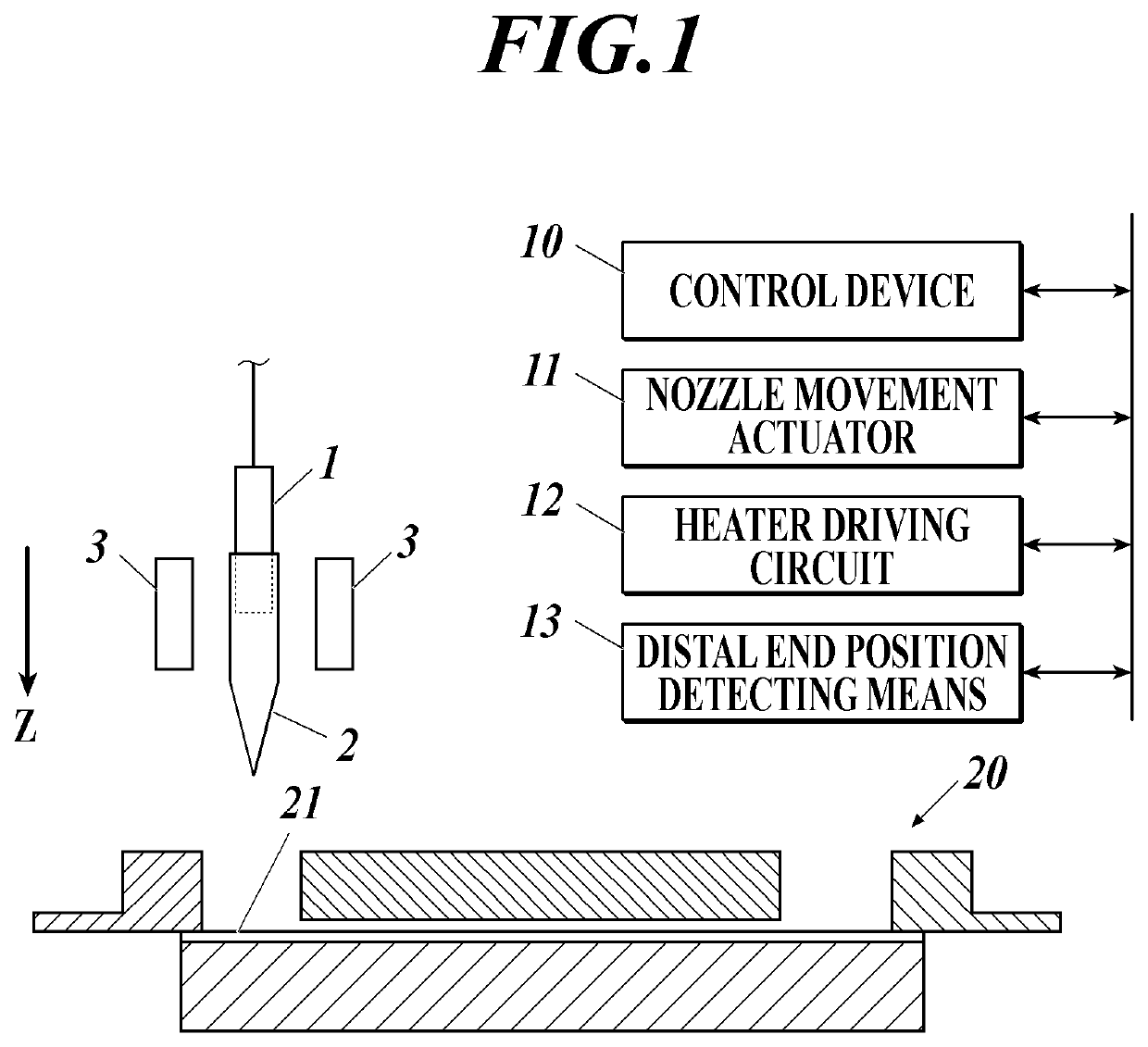
[0038]As shown in FIG. 1, a pipette tip 2 is attached to a tip portion of a pipette nozzle 1. The heater 3 is disposed close to the attaching position of the pipette tip 2 ahead of the tip of the pipette nozzle 1. The heater 3 is configured to heat the pipette tip 2 attached to the pipette nozzle 1.
[0039]The control device 10 controls the operation of an analyzer that performs the reaction method of the present embodiment. With regard to the present invention, the control device 10 controls moveme...
PUM
 Abstract
Description
Claims
Application Information