Medical support device

Active Publication Date: 2017-01-19
CANON USA +1
View PDF0 Cites 31 Cited by
  • Summary
  • Abstract
  • Description
  • Claims
  • Application Information

AI Technical Summary

Benefits of technology

[0011]A medical support device is provided that comprises: a first rotational element having a first rotation axis and a first rotational degree of freedom; a second rotational element having a second rotation axis and a second rotational degree of freedom that is attached to the first rotational element wherein the second rotation axis intersects with the first rotation axis; and at least one needle guide that is attachable to the second rotational element and is configured to guide the direction of insertion of a needle-like instrument. In this device, the at least one needle guide includes at least one guide portion that guides a first needle

Problems solved by technology

However, in the case of percutaneous puncture treatment, the puncture target site is not directly visible, and therefore puncture needs to be performed on the basis of a medical image obtained using an MRI machine, a CT machine, or the like.
However, since these medical imaging machines are used, an image cannot be obtained in real time.
In both cases, it is difficult to precisely

Method used


Image

  • Medical support device
  • Medical support device
  • Medical support device

Examples


first embodiment

Configuration

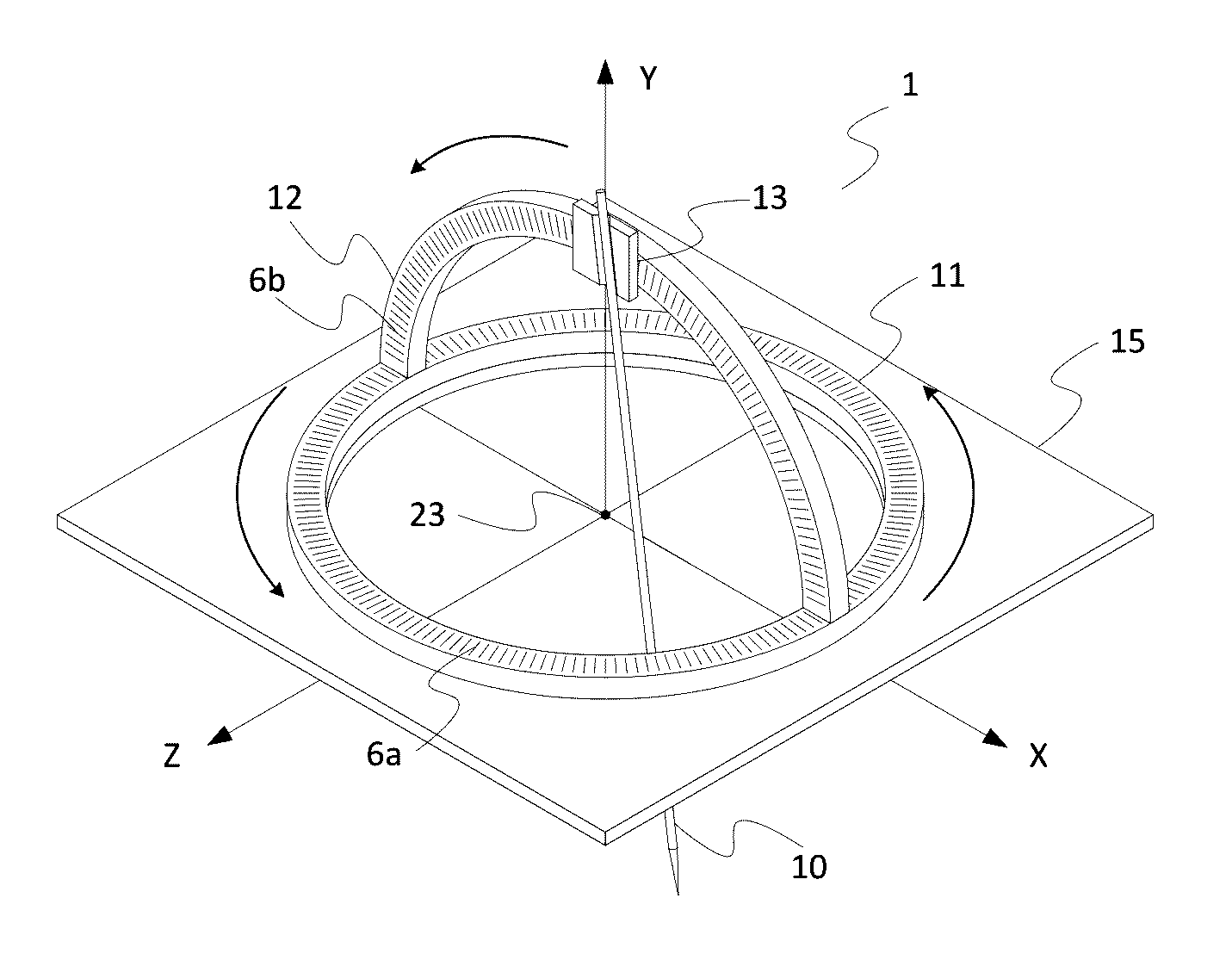
[0034]A first embodiment of the present invention will be described with reference to FIG. 1, FIGS. 5A and 5B, and FIG. 6 to Fig. First, the schematic configuration of a mechanical portion of a medical support device of this embodiment will be described with reference to FIG. 1.

Mechanical Configuration

[0035]In FIG. 1, the structure of a movable portion in each rotational element, or rotational element is omitted for simplification. First, a base 15 of a mechanical portion 1 is fixed and installed on an object to be punctured with a fixing unit (not shown).

[0036]A stationary portion of an annular, or ring shaped first rotational element 11 (also defined as a rotation mechanism) is attached to the base 15.

[0037]Next, a stationary portion of an arcuate second rotational element 12 (also defined as a rotation mechanism) is attached to a movable portion of the rotational element 11. At this time, the rotational element 11 and the rotational element 12 are configured such tha...

second embodiment

Configuration

[0085]A second embodiment of the present invention will be described with reference to FIG. 6 to FIG. 8A. First, the schematic configuration of a mechanical portion of a medical support device of this embodiment will be described with reference to FIG. 6 and FIG. 7.

Mechanical Configuration

[0086]In FIG. 6, the structure of a movable portion in each rotational element is omitted for simplification. The embodiments of the rotational elements as described in U.S. Pat. Pub. 2014 / 027979 are herein incorporated by reference. In use, a base 15 of a mechanical portion 1 is first fixed and installed on an object to be punctured with a fixing unit (not shown). This includes, for example, the torso of a patient.

[0087]FIG. 7 is a sectional view of the configuration of FIG. 6 cut along the ZY-plane.

[0088]A stationary portion of an annular, or ring shaped first rotational element 11 is attached to the fixing unit.

[0089]A stationary portion of an annular second rotational element 12 is...

third embodiment

[0107]The third embodiment of the present invention will be described with references to FIG. 13 to FIG. 14. First, the apparatus of using interchangeable needle guides of different designs will be described with reference to FIG. 13. However, the needle guides as described in the first and second embodiments may also be combined with the teachings of this embodiment.

[0108]In FIG. 13, an example of apparatus of a detachable needle guide is presented. For simplicity, only the two mating surfaces 24 and 25 are shown. When combined, these surfaces form a second rotational element 12 as described, for example, in FIG. 6. The lower mating surface 24 is attached to the first rotational element or base (not shown).

[0109]The needle guide can be attached and detached at the will of the user. For example, the needle guide can be slid into and out of a groove, onto a pin-like structure, or it can contain a snap closure for securing and removing from the apparatus. The removable mating surface ...


PUM


Abstract

There is provided a medical support device for holding and positioning a needle. This device is particularly useful for positioning needles in a less invasive puncture treatment. This device comprises two rotational elements and at least one needle guide attached to a rotational element and. The needle guide guides the direction of insertion of a needle-like instrument and includes a guide portion that guides a needle or other needle-like instrument where the puncture point of the needle in a first position is different from the puncture point when the needle guide guides the needle in a second position.

Description

BACKGROUND OF THE INVENTION[0001]Field of the Invention[0002]The present invention relates to a medical support device for holding and positioning a needle. More specifically, the present invention relates to positioning of one or more needles in a puncture treatment.[0003]Description of the Related Art[0004]In medical treatment, in order to improve the QOL (quality of life) of the patient, the need for less invasive treatment is increasing. In such a situation, percutaneous puncture treatments such as percutaneous puncture ablation and percutaneous puncture cryosurgery have been developed as less invasive treatments.[0005]However, in the case of percutaneous puncture treatment, the puncture target site is not directly visible, and therefore puncture needs to be performed on the basis of a medical image obtained using an MRI machine, a CT machine, or the like. However, since these medical imaging machines are used, an image cannot be obtained in real time. Although an image can be o...

Claims


Application Information

Patent Timeline
IPC IPC(8): A61B90/11A61B17/34
CPCA61B90/11A61B2017/3407A61B17/3403A61B2017/00398A61B90/94A61B18/02A61B18/14A61B18/1477A61B2018/0212A61B90/39A61B2090/3954
Inventor ONUMA, KAZUFUMIKATO, TAKAHISAHATA, NOBUHIKOTUNCALI, KEMALNINNI, BRIANTIA, PETER
Owner CANON USA
Why Eureka
Try Eureka