
Mixer, mixing device and unit for measuring medical component

a technology for measuring medical components and mixers, which is applied in the direction of machines/engines, combustion air/fuel air treatment, chemical/physical processes, etc., can solve the problems of thrombosis, complicated device structure, and difficulty in placing a rotatable mixer in a channel with a small diameter, and achieve accurate glucose concentration measurement and small time constant

Active Publication Date: 2009-09-03
NIKKISO COMPANY
View PDF13 Cites 15 Cited by
  • Summary
  • Abstract
  • Description
  • Claims
  • Application Information

AI Technical Summary

Benefits of technology

[0010]An objective of the present invention is to provide a mixer without rotating structures such as mixing blades, capable of mixing quickly several liquids including at least one liquid that is prone to gel or solidify easily. It is also the objective to provide a mixing device capable of quickly mixing several liquids including at least one liquid that is prone to gel or solidify by utilizing air bubbles, which mixing device has a structure by which the liquids are mixed uniformly without causing the liquid to gel or solidify. A still further objective is to provide a medical component-measuring unit capable of reducing the formation of thrombi and accurately measuring the concentration of glucose, and with a small time constant, made by incorporation of the mixer or the mixing device, which unit, in turn, can be incorporated into medical support devices, such as artificial endocrine pancreas devices.
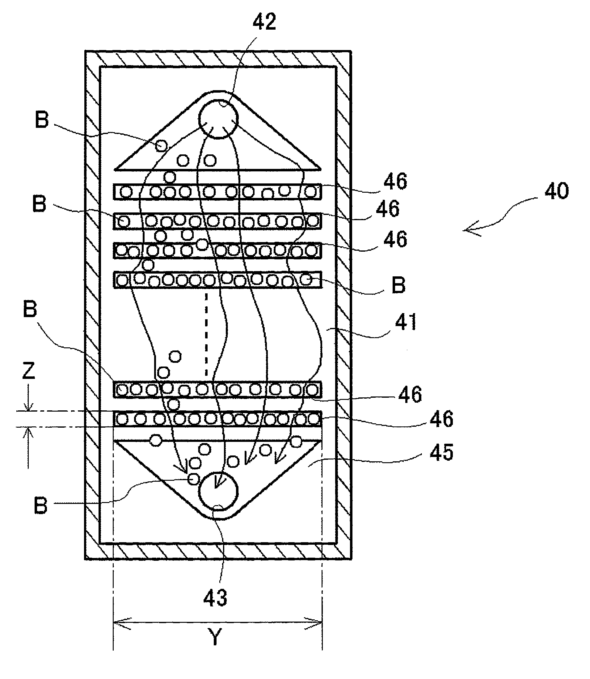
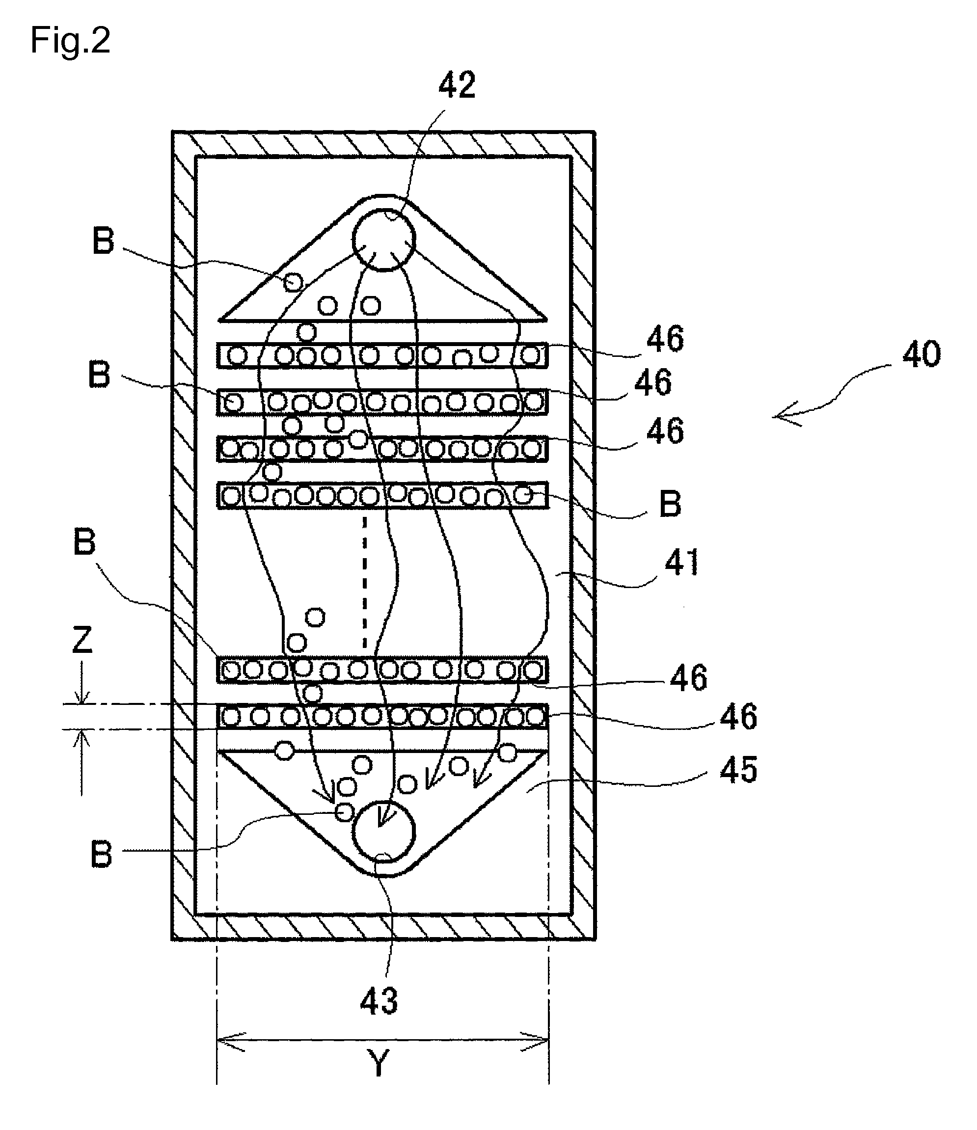
[0021]Although the mixer according to the present invention may be placed horizontally, it can also be positioned aslant, which is preferable. In the latter case, the angle at which the mixer is inclined should be from 20 degrees to 90 degrees to the horizontal face. When the mixer is inclined in this way, it should preferably be so positioned that the liquid inlet is at an upper side, liquid outlet at a lower side, and the air bubble-trapping structure is in or on the ceiling of the mixing channel. When the mixer is in such a position, the liquids supplied from the liquid inlet, which is located at an upper side, fall gravitationally or by the force of discharging the liquids exerted by a suck-and-discharge device such as a pump. Air bubbles that have been introduced into the mixer and exist in the mixing channel are temporarily trapped by the air bubble-trapping structure. The trapped air bubbles are released from the trapping structure after a predetermined period of time and let to be outside the trapping structure temporarily. Some of the released air bubbles tend to rise toward the surface against the downward flow of the liquids supplied from the liquid inlet, which is located at the upper place, while the others move downward with the downward flow of the liquids. The air bubbles moving upward and those moving downward are caught by the trapping structure and kept in it for a short time again. Then, the trapped air bubbles are released from the trap structure again, and some of the re-released air bubbles tend to rise toward the surface against the downward flow of the liquids supplied from the liquid inlet, which is located at the upper place, while the others move downward with the downward flow of the liquids, in the same way. The air bubbles are finally discharged from the liquid outlet with the downward flow. Irregular movements of the air bubbles and local disturbances of the fluid flow caused by complicated movements of the air bubbles that repeat upward and downward movements, or the movement of rising toward the surface against the liquid flow and that of descending with it, further expedite mixing of the liquids. Moreover, when the liquids include blood, the formation of thrombi can be prevented because thrombus-causing substances that may possibly be produced in the mixing channel adhere to the air bubbles and are discharged from the liquid outlet with them.
[0023]In conclusion, the present invention provides a mixer which is capable of mixing liquids each in very small amounts quickly and uniformly, and has a structure capable of preventing a liquid that is prone to gel or solidify from gelling or solidifying when it is mixed with other liquids, actually a very simple structure in order to prevent the gelation and solidification during its use.
[0027]The medical component-measuring unit, with the mixer or the mixing device incorporated, is capable of accurately measuring the concentration of glucose having a small time constant, once it is attached to a medical support device such as an artificial endocrine pancreas device.

Problems solved by technology

Besides, it is difficult to place a rotatable mixer in a channel with a small diameter to mix several kinds of liquids each in small amounts while they are being transferred.
Even if such a mixer is placed in the channel, it makes the structure of the device complicated.
When a blood sample and a reagent are mixed with a mixing device or by other structures, the device and structures become obstacles against the fluid flow, and the liquids are caught by the obstacles and remain on places thereof, which leads to the formation of thrombi.
Artificial endocrine pancreas devices, employing such a long coiled tube as mixing device, have a large time constant, which is problematic with this kind of devices.

Method used


Image

  • Mixer, mixing device and unit for measuring medical component
  • Mixer, mixing device and unit for measuring medical component
  • Mixer, mixing device and unit for measuring medical component

Examples


Embodiment Construction

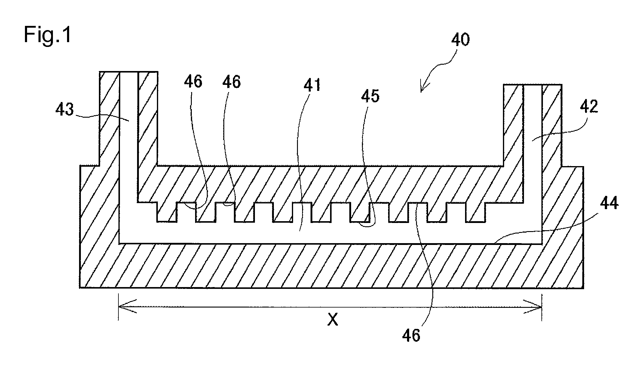
[0052]As shown in FIG. 1, the mixer 40 has a mixing channel 41, a liquid inlet 42 and a liquid outlet 43. The mixing channel 41 is in the shape of a chamber with a bottom 44 and a ceiling 45. The ceiling 45 has a plan view in the shape of a general rectangle with a longer side parallel to the liquid flow and a shorter side perpendicular to the liquid flow. The ceiling 45 is provided with the liquid inlet 42 at one end thereof, and the liquid outlet 43 at the other end thereof. When the mixing channel 41 is designed so that liquids in a very small amount flow through it, the mixing channel typically has such dimensions that the distance between the bottom 44 and the ceiling 45 is from 0.1 to 2 mm, the length along the axis of the channel between the liquid inlet 42 and the liquid outlet 43 is from 5 to 50 mm, the inner diameter of the opening of the liquid inlet 42 is from 0.1 to 3 mm, and the inner diameter of the opening of the liquid outlet 43 is from 0.1 to 3 mm. The mixer of the...


PUM

PropertyMeasurementUnit
angleaaaaaaaaaa
lengthaaaaaaaaaa
angleaaaaaaaaaa

Abstract

This invention provides a mixer without a rotational or similar structure, capable of mixing quickly several liquids including at least one liquid being prone to gel or solidify, a mixing device with the mixer incorporated, and a medical component-measuring unit capable of reducing the formation of thrombi and accurately measuring the concentration of glucose, and with a small time constant, which unit can be incorporated into medical support devices, such as artificial endocrine pancreas devices. The mixer has an air bubble-trapping structure for temporarily trapping air bubbles supplied to a surface of a mixing channel through which liquids to be mixed flow. The mixing device has the mixer, an air bubble supplier or generator to make air bubbles exist in the mixing channel, and a liquid supplier for supplying liquids to be mixed to a liquid inlet. The medical component-measuring unit has the mixer or the mixing device.

Description

CROSS REFERENCE TO PRIOR RELATED APPLICATIONS[0001]This is a U.S. national phase application under 35 U.S.C. §371 of International Patent Application No. PCT / JP2007 / 000367 filed Apr. 4, 2007, and claims the benefit of Japanese Patent Application No. 2006-104741 filed Apr. 5, 2006. The International Application was published in Japanese on Nov. 8, 2007 as WO 2007 / 125642 A1 under PCT Article 21 (2). The contents of these priority applications are incorporated, in their entireties, into the present disclosure by reference.BACKGROUND OF THE INVENTION[0002]1. Field of the Invention[0003]The present invention relates to a mixer, a mixing device, and a medical component-measuring unit. More particularly, the present invention relates to a mixer capable of mixing quickly several liquids including at least one liquid that is prone to easily gel or solidify, which mixer has a structure preventing the liquid from gelling. The invention also relates to a mixing device, with the mixer incorporat...

Claims


Application Information

Patent Timeline
Patent Type & Authority Applications(United States)
IPC IPC(8): B05B7/24B01F33/40
CPCB01F5/0611B01F13/0059G01N2035/00544B01F2005/0621B01F2005/0636B01F13/0222B01F25/4311B01F25/4317B01F25/431971B01F33/403B01F33/30
Inventor MURAKAMI, MOTOAKI
Owner NIKKISO COMPANY
Learn More