Valve lash adjuster for vehicles

Inactive Publication Date: 2017-01-19
HYUNDAI MOTOR CO LTD
View PDF1 Cites 9 Cited by
  • Summary
  • Abstract
  • Description
  • Claims
  • Application Information

AI Technical Summary

Benefits of technology

[0008]Various aspects of the present invention are directed to providing a lash adjuster using hydraulic pressure applicable to a co

Problems solved by technology

However, it is difficult to apply such an HLA to a commercial diesel engine h

Method used


Image

  • Valve lash adjuster for vehicles
  • Valve lash adjuster for vehicles
  • Valve lash adjuster for vehicles

Examples


Embodiment Construction

[0026]Reference will now be made in greater detail to a valve lash adjuster according to an exemplary embodiment of the present invention, an example of which is illustrated in the accompanying drawings. Wherever possible, the same reference numerals will be used throughout the drawings and the description to refer to the same or like parts.

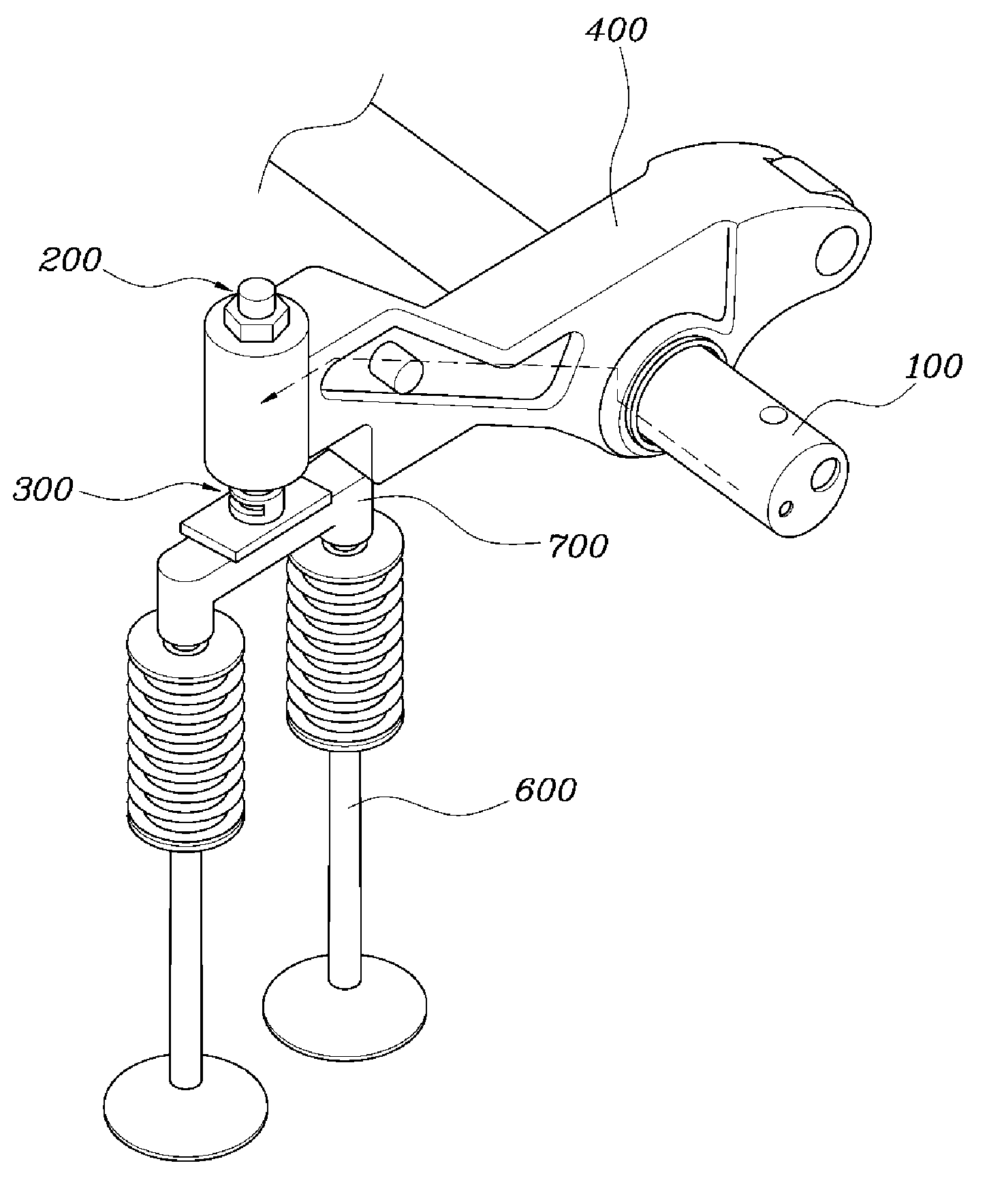
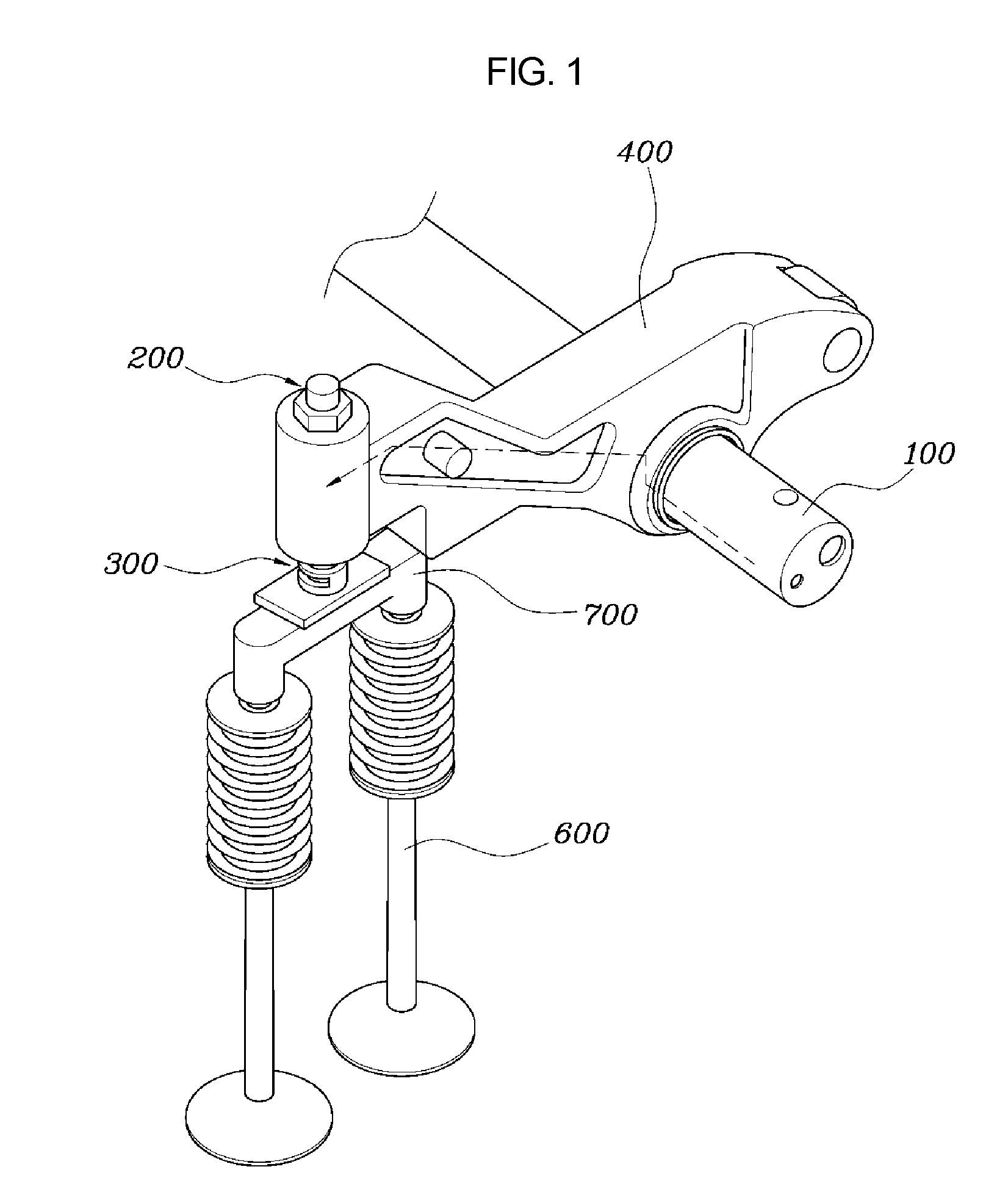
[0027]FIG. 1 is a perspective view illustrating an application of a valve lash adjuster according to an exemplary embodiment of the present invention, FIG. 2 is a perspective view illustrating the valve lash adjuster illustrated in FIG. 1, FIGS. 3A, 3B, and 3C are exploded perspective and cross-sectional views illustrating the valve lash adjuster illustrated in FIG. 2, and FIGS. 4A, 4B, and 4C illustrate the operation of the valve lash adjuster illustrated in FIG. 2.

[0028]The valve lash adjuster according to the present exemplary embodiment includes a piston 200 and a cylinder 300. The piston 200 includes a body 210 having an open surface 211 in ...


PUM


Abstract

A valve lash adjuster for vehicles may include a piston having a body and an opening/closing unit. The body has an open surface in a bottom and an oil passage extending from a rocker arm shaft to the open surface, such that oil flows through the oil passage. The opening/closing unit is disposed on the oil passage to selectively open the oil passage depending on a pressure of the oil. A cylinder accommodates the piston. The cylinder slides downward to form an oil chamber between an inner side surface thereof and the piston. The oil chamber contains the oil therein.

Description

CROSS REFERENCE TO RELATED APPLICATION[0001]The present application claims priority to Korean Patent Application No. 10-2015-0099718, filed Jul. 14, 2015, the entire contents of which is incorporated herein for all purposes by this reference.BACKGROUND OF THE INVENTION[0002]Field of the Invention[0003]The present invention generally relates to a hydraulic valve lash adjuster for a vehicle. More particularly, the present invention relates to a valve lash adjuster for a diesel engine, such as a commercial diesel engine, having high power and a large engine displacement.[0004]Description of Related Art[0005]In general, an engine has a valve opening / closing mechanism enabling the operation of intake and exhaust valves using a crank shaft rotating following a piston motion. Such a valve opening / closing mechanism includes a cam shaft connected to the crank shaft by means of a belt to cooperate with the crank shaft, rocker arms rocking within a set range in response to the cam shaft, and i...

Claims


Application Information

Patent Timeline
IPC IPC(8): F01L1/24
CPCF01L1/24F01L1/2416F01L1/181F01L1/26F01L2810/02
Inventor YOON, SEOCK JOONG
Owner HYUNDAI MOTOR CO LTD
Why Eureka
Try Eureka