Ignition coil for internal combustion engine

a technology for internal combustion engines and ignition coils, which is applied in the direction of ignition safety means, machines/engines, spark plugs, etc., can solve the problems of reduced number of ignition coil parts, escape of resin outside the case, damage or breakage of the case, etc., and achieves easy control, high accuracy of diameter, and minimizing mechanical stress

Active Publication Date: 2017-01-19
DENSO CORP
View PDF5 Cites 10 Cited by
  • Summary
  • Abstract
  • Description
  • Claims
  • Application Information

AI Technical Summary

Benefits of technology

[0006]It is therefore an object to provide an ignition coil for internal combustion engines which is designed to facilitate hermetically sealing a gap between a resistor and a case of the ignition coil and ensure the stability in such sealing.
[0008]The ignition coil, as described above, includes the resinous coating which covers the outer periphery of the resistor. The resistor is fit in the high-voltage tower through the resinous coating. It is, thus, easy to ensure a required dimensional relation between the inner periphery of the high-voltage tower and the outer periphery of the resistor. Specifically, before the resistor 3 is finished, the radial dimension or diameter of the resistor is selected to be smaller than the diameter of the inner periphery of the high-voltage tower in view of a dimensional tolerance of a gap between the inner periphery of the high-voltage tower and the resistor. The periphery of the resistor is then covered with the resinous coating whose thickness is easy to control, thereby achieving a desired outer diameter of the resistor.
[0009]The resistor equipped with the resinous coating which, as apparent from the above discussion, has the highly accurate diameter is fit in the high-voltage tower, thus minimizing the degree of mechanical stress which arises from the fitting of the resistor into the high-voltage tower and acts on the high-voltage tower and also ensuring the stability of sealing between the resistor and the high-voltage tower. This obviates the risk of leakage of the resinous filler into the high-voltage tower when the resinous filter is packed in the case.
[0010]The resistor is fit in the high-voltage tower through the resinous coating, thus causing the stress acting on the resistor and the high-voltage tower to be absorbed by the resinous coating, thereby avoiding exertion of an undesirable degree of stress on the high-voltage tower. This enables the case, i.e., the ignition coil to be reduced in size without the need for increasing the thickness of the high-voltage tower to ensure a desired degree of stiffness of the case.
[0011]The structure of the ignition coil, therefore, facilitates hermetically sealing between the resistor and the case and ensures the stability of the sealing.

Problems solved by technology

This also results in a decrease in the number of parts of the ignition coil.
The ignition coil is so designed as to press-fit the resistor directly into the front open end of the case and, therefore, faces the drawback in that the resistor may be too large in size to be inserted into the open end of the case depending upon, for example, an error in machining the resistor or mechanical stress arising from the press-fitting of the resistor into the open end of the case may be undesirably increased, which leads to damage to or breakage of the case.
Alternatively, too small a size of the resistor may result in a failure to be tightly fitted into the open end of the case, which leads to escape of the resin outside the case when the resin is packed into the case.
This obviates the risk of leakage of the resinous filler into the high-voltage tower when the resinous filter is packed in the case.

Method used


Image

  • Ignition coil for internal combustion engine
  • Ignition coil for internal combustion engine
  • Ignition coil for internal combustion engine

Examples


first embodiment

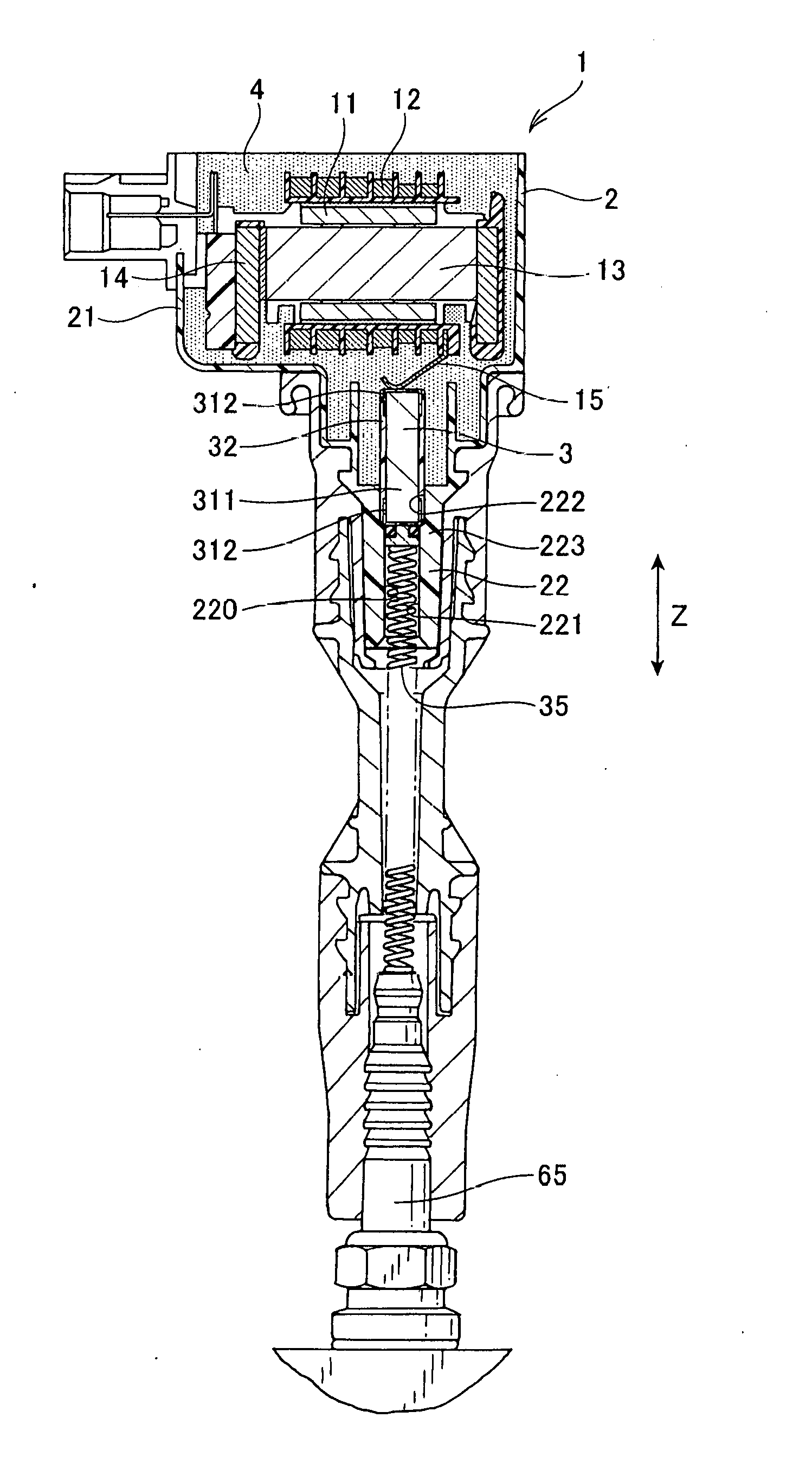
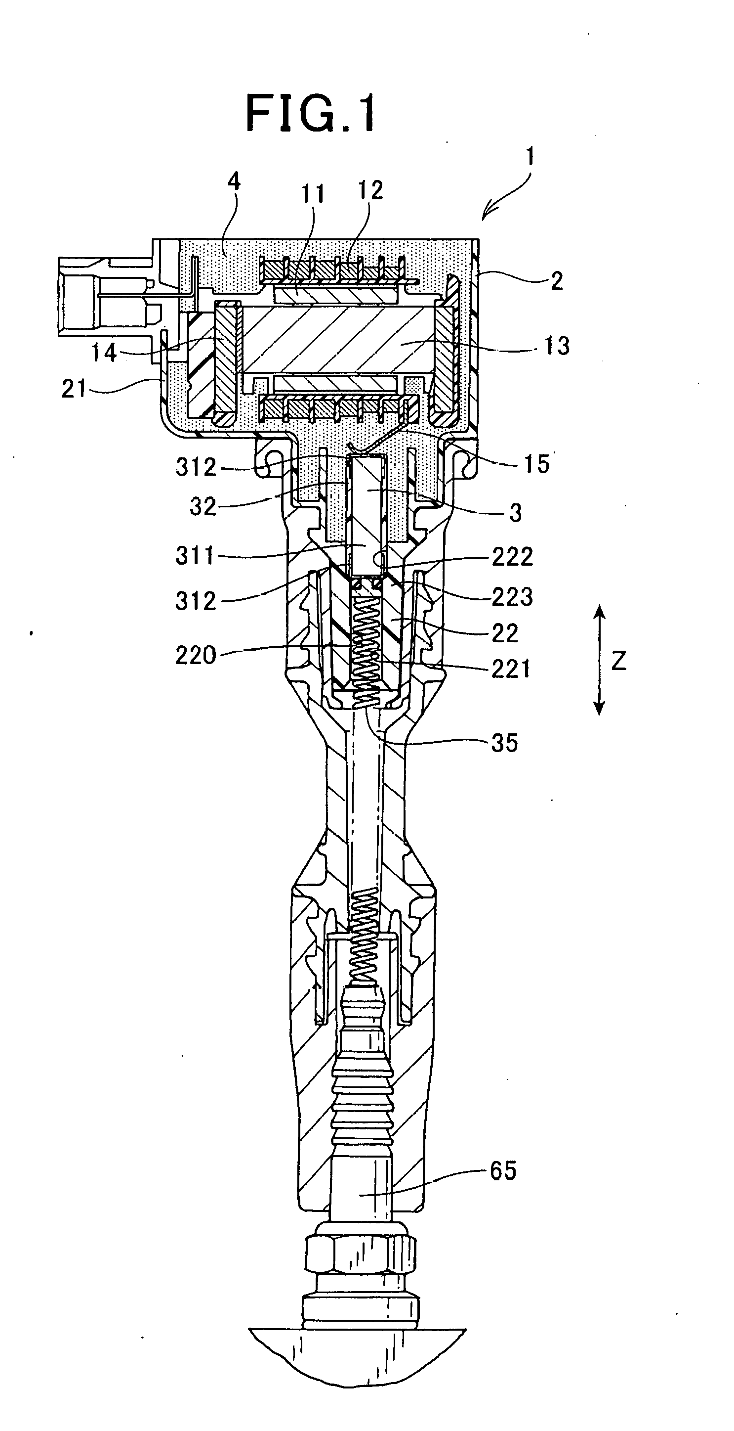
[0024]Referring to the drawings, wherein like reference numbers refer to like parts in several views, particularly to FIGS. 1 to 5, there is shown an ignition coil 1 for internal combustion engine according to the first embodiment.

[0025]The ignition coil 1, as clearly illustrated in FIG. 1, includes the primary coil 11 and the secondary coil 12 which are magnetically coupled together, the case 2, the resistor 3, and the filled resin 4. The case 2 includes the case body 21 in which the primary coil 11 and the secondary coil 12 are disposed and the high-voltage tower 22 which is of a tubular shape and extends from the case body 21. The resistor 3 is tightly fit in the high-voltage tower 22 and electrically joined to the secondary coil 12. The filled resin 4 which will also be referred to as a resinous filler below is packed in the case body 21 to hermetically seal the primary coil 11 and the secondary coil 12. The resistor 3, as illustrated in FIGS. 1 to 5, has a resinous coating 32 w...

second embodiment

[0052]FIG. 8 illustrates the ignition coil 1 according to the second embodiment.

[0053]The resistor 3 has a portion of the length of the resinous coating 32 which is located between the electrode caps 312 opposed to each other in the axial direction Z and which is fit in the high-voltage tower 22. In other words, the resistor 3 is press-fit at a portion thereof unoccupied by the electrode caps 312 in the high-voltage tower 22 through the resinous coating 32.

[0054]The resinous coating 32 is made up of two small-diameter portions 322 and a large-diameter portion 323 disposed between the small-diameter portions 322. The small-diameter portions 322 are opposed to each other in the axial direction Z and cover the respective electrode caps 312. The small-diameter portions 322 will also be referred to as coating end portions below. The large-diameter portion 323 bulges radially from the small-diameter portions 322. The small-diameter portions 322 and the large-diameter portions 323 cover th...

third embodiment

[0061]FIG. 9 illustrates the ignition coil 1 according to the third embodiment.

[0062]The resinous coating 32 of the ignition coil 1 of this embodiment has a positioner324 which works to position the resistor 3 relative to the high-voltage tower 22 in the axial direction Z. The through hole 220 of the high-voltage tower 22 is shaped to have an inner diameter kept constant in the axial direction Z.

[0063]The resinous coating 32, like in the second embodiment, includes two small-diameter portions 322 and the large-diameter portion 323. The resinous coating 32 also includes the cylindrical positioner 324 which bulges radially from the large-diameter portion 323. The positioner 324 is formed on a central portion of a length of the large-diameter portion 323 extending in the axial direction Z.

[0064]The large-diameter portion 323 has an outer diameter slightly greater than the inner diameter of the through hole 220 before the resistor 3 is installed in the high-voltage tower 22. The positio...


PUM

PropertyMeasurementUnit
voltageaaaaaaaaaa
circumferenceaaaaaaaaaa
sizeaaaaaaaaaa

Abstract

An ignition coil for internal combustion engines is provided which includes a primary and a secondary coils magnetically coupled with each other, a case, a resistor, and a resinous filler. The case includes a case body in which the primary and secondary coils are disposed and a tubular high-voltage tower extending from the case body toward a head of the ignition coil. The resistor 3 is press-fitted into the high-voltage tower and electrically connected to the secondary coil. The resinous filler is packed in the case body to hermetically seal the primary coil and the secondary coil. The resistor includes a resinous coating which covers an outer circumference of the resistor and is press-fit in the high-voltage tower through the resinous coating. This facilitates hermetically sealing a gap between the resistor body and the case and ensures the stability of the sealing.

Description

CROSS REFERENCE TO RELATED DOCUMENT[0001]The present application claims the benefit of priority of Japanese Patent Application No. 2015-141853 filed on Jul. 16, 2015, the entire disclosure of which is incorporated herein by reference.BACKGROUND[0002]1 Technical Field This disclosure relates generally to an ignition coil for an internal combustion engine.[0003]2 Background Art[0004]For instance, Japanese Patent No. 5340889 discloses an ignition coil which includes a primary coil, a secondary coil, and a case. The primary and secondary coils are magnetically coupled with each other and disposed inside the case. The case is filled with resin to hermetically seal the primary and secondary coils. The case also has disposed therein a resistor which closes a front open end of the case in order to avoid leakage of the filled resin outside the case. This also results in a decrease in the number of parts of the ignition coil.[0005]The ignition coil is so designed as to press-fit the resistor ...

Claims


Application Information

Patent Timeline
Patent Type & Authority Applications(United States)
IPC IPC(8): F02P3/055H01F27/40H01F27/02H01F38/12
CPCF02P3/055H01F27/02H01F27/40H01F38/12H01F27/022F02P3/04F02P7/02F02P11/00F02P13/00H01T13/04H01T13/05
Inventor AKIMOTO, KATSUNORI
Owner DENSO CORP
Why Eureka
Try Eureka