LED filament and LED bulb with LED filament

a technology of led filament and led bulb, which is applied in the field of led illumination, can solve the problems that the cost cannot be avoided, and achieve the effect of reducing costs without sacrificing structural strength

Active Publication Date: 2017-01-19
KAISTAR LIGHTING (XIAMEN) CO LTD +1
View PDF3 Cites 52 Cited by
  • Summary
  • Abstract
  • Description
  • Claims
  • Application Information

AI Technical Summary

Benefits of technology

[0028]In conclusion, according to a LED filament and a LED bulb with the LED filament of the embodiments above, as the hardness of the first lateral section is less than that of the second lateral section, the LED filament above can be designed according to various requirements of structural strength, which can reduce costs without sacrificing structural strength.

Problems solved by technology

However, during process of manufacturing a conventional LED bulb, a LED filament mounted on a column can be commonly manual, and an external force is needed in aligning welding, which can easily fail a component caused by the copper frame bend.
Moreover, high costs cannot be avoided if power of a single conventional LED filament is increased.

Method used


Image

  • LED filament and LED bulb with LED filament
  • LED filament and LED bulb with LED filament
  • LED filament and LED bulb with LED filament

Examples


first embodiment

An First Embodiment

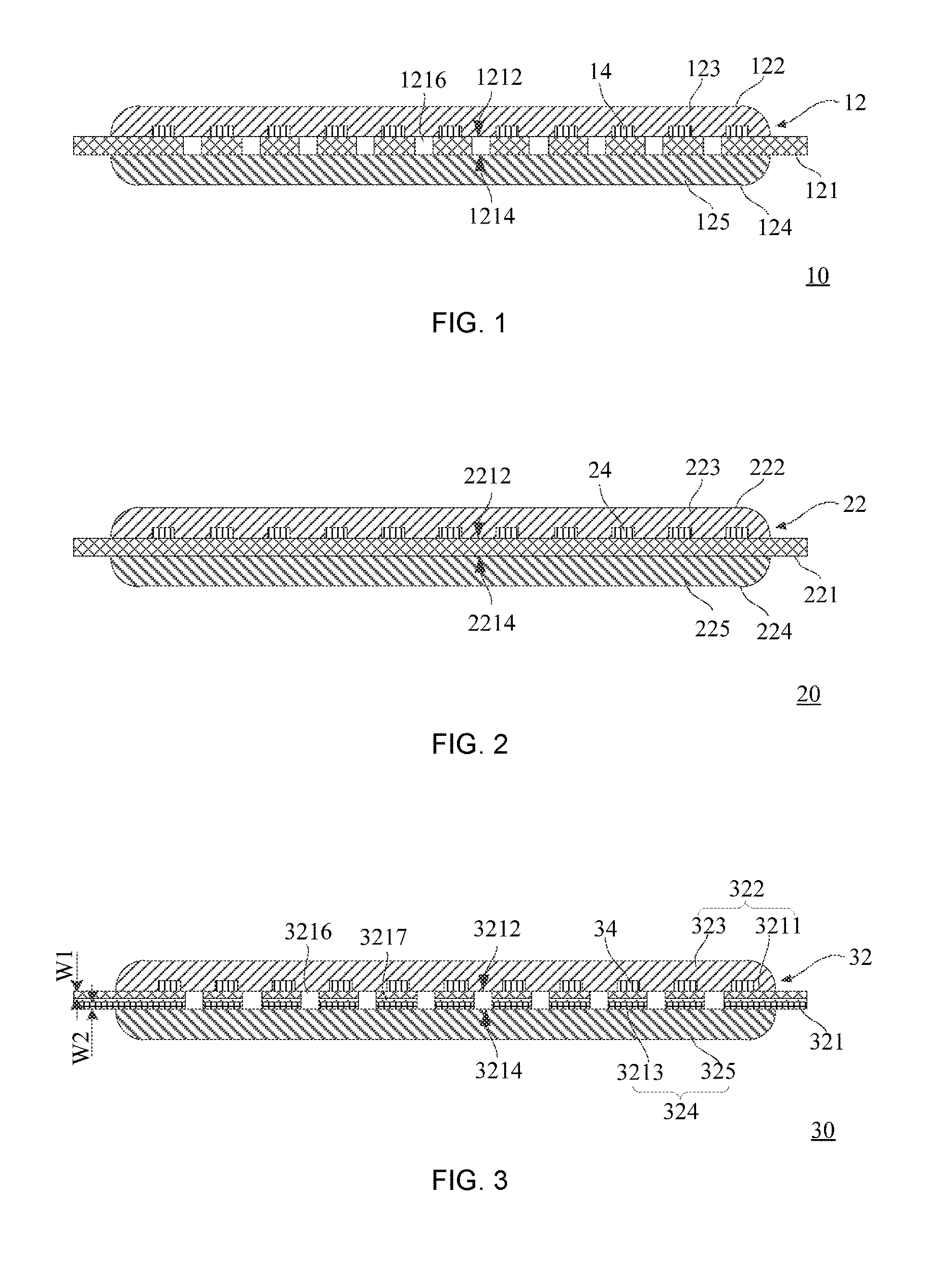
[0040]Referring to FIG. 1, a LED filament 10 provided by the first embodiment of the disclosure includes: a carrier 12, multiple LED chips 14 disposed on the carrier 12. The carrier 12 includes a first lateral section 122 and a second lateral section 124 opposite to the first lateral section 122. The LED chips 14 are formed on the first lateral section 122. Hardness of the first lateral section 122 is less than that of the second lateral section 124.

[0041]As the hardness of the first lateral section 122 is less than that of the second lateral section 124, the LED filament 10 above can be designed according to various requirements of structural strength, which can reduce costs without sacrificing structural strength of the LED filament 10.

[0042]In the embodiment, the carrier 12 includes a substrate 121, a first adhesive 123 and a second adhesive 125. The substrate 121 contains a first surface 1212 and a second surface 1214 opposite to the first surface 1212. The LE...

second embodiment

A Second Embodiment

[0047]FIG. 2 is a LED filament 20 provided by the second embodiment of the disclosure. The LED filament 20 is similar with the LED filament 10, including a carrier 22, multiple LED chips 24 disposed on the carrier 22. The carrier 22 includes a substrate 221, a first adhesive 223 and a second adhesive 225. The substrate 221 contains a first surface 2212 and a second surface 2214 opposite to the first surface 2212. The LED chips 24 are disposed on the first surface 2212 of the substrate 221. The first adhesive 223 covers the first surface 2212 and the LED chips 24, the second adhesive 225 covers the second surface 2214. The first adhesive 223 forms a first lateral section 222, the second adhesive 225 forms the second lateral section 224. A difference of the LED filament 20 and the LED filament 10 is: the substrate 221 of the LED filament 20 is formed by a transparent material, such as transparent ceramic, sapphire or glass. And since the substrate 221 is formed by a...

third embodiment

A Third Embodiment

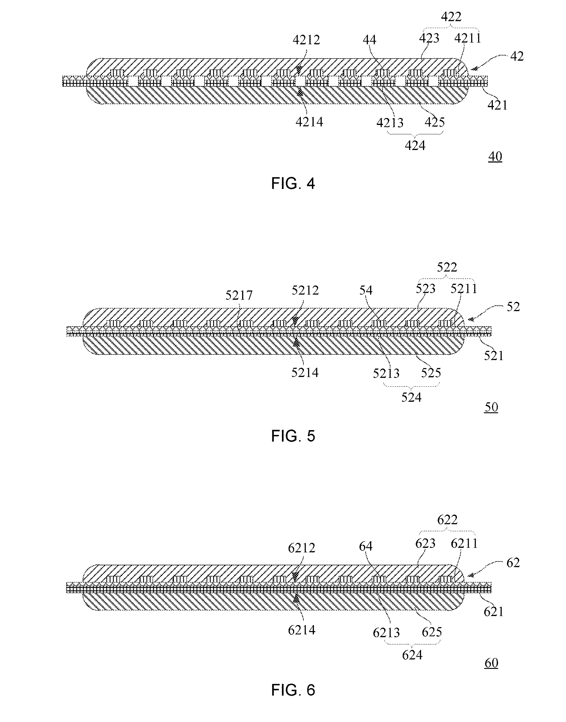
[0048]FIG. 3 is a LED filament 30 provided by the third embodiment of the disclosure. The LED filament 30 is similar with the LED filament 10, including a carrier 32, multiple LED chips 34 disposed on the carrier 32. The carrier 32 includes a first lateral section 322 and a second lateral section 324 opposite to the first lateral section 322. The LED chips 34 are disposed on the first lateral section 322. Hardness of the first lateral section 322 is less than that of the second lateral section 324.

[0049]In the embodiment, the carrier 32 includes a substrate 321, a first adhesive 323 and a second adhesive 325. The substrate 321 contains a first bracket 3211 and a second bracket 3213 connected with the first bracket 3211. The first bracket 3211 contains an upper surface 3212 away from the second bracket 3213, the second bracket 3213 contains a bottom surface 3214 away from the first bracket 3211. The LED chips 34 are disposed on the upper surface 3212 of the first br...


PUM


Abstract

The present disclosure relates to a LED filament and a LED bulb with the LED filament. The LED filament includes a carrier, LED chips disposed on the carrier, the carrier includes a first lateral section and a second lateral section opposite to the first lateral section, the LED chips are formed on the first lateral section, hardness of the first lateral section is less than that of the second lateral section. The disclosure further provides a LED bulb with the LED filament above. The LED filament above has benefits of improving structural strength and decreasing costs.

Description

FIELD OF THE DISCLOSURE[0001]The present disclosure relates to a LED illumination technical field, and more particularly to a LED filament and a LED bulb with the LED filament.BACKGROUND OF THE DISCLOSURE[0002]A light emitting diode (LED) is a solid-state semiconductor device that can transform electrical energy into visible light. A LED is an ideal light source that can take the place of a conventional light source since it contains benefits such as less energy consumption, longer service life and little environmental contamination, applied in various realms.[0003]A conventional LED bulb can include a LED filament, a stem, a transparent lampshade such as a spherical lampshade, and a lamp holder such as a thread lamp holder; the transparent lampshade, the stem and the lamp holder are connected firmly, the stem is disposed in the transparent lampshade and equipped with electrodes that can be connected to the LED filament in order to supply power to the LED filament.[0004]A LED filame...

Claims


Application Information

Patent Timeline
Patent Type & Authority Applications(United States)
IPC IPC(8): F21V3/00
CPCF21K9/232H01L25/0753H01L33/483
Inventor YANG, CHIEN-LICHUNG, YU-CHUNLI, YU MIN
Owner KAISTAR LIGHTING (XIAMEN) CO LTD
Why Eureka
Try Eureka