
Eureka
For R&D, Eureka makes reading and utilizing patents & technical documents easy.
Eureka AIR
Designed for self-driven R&D workflows. Generate viable solutions, solve complex R&D challenges, empower your innovation with AI.

Eureka Materials
Designed for material experts only. Revolutionize your material R&D, from search, analyze, to developing new materials.

TechResearch
Generate reliable direction feasibility study reports for your R&D in just a few steps.

TechSeek
Discover and master advanced knowledge NOW. Basics, ideas, possibilities, all at once.

TechMind
As an expert in R&D Theories, TechMind can generates customized viable solutions instantly.

TechRisk
Analyze your overall solution with one click, know your potential R&D risks in advance.

TechMonitor
Get weekly tech updates, stay abreast of the latest tech innovations and key insights.
Medical image diagnosis assistance device, magnetic resonance imaging apparatus and medical image diagnosis assistance method
- Summary
- Abstract
- Description
- Claims
- Application Information
AI Technical Summary
Benefits of technology
Problems solved by technology
Method used
Image

Examples
first embodiment
[0033]A first embodiment to which the present invention is applied is described as below. Unless otherwise specifically noted, the same or similar reference numerals in the drawings illustrating the embodiments hereof are used to refer to the same or similar components which are explained only once to avoid repetition.
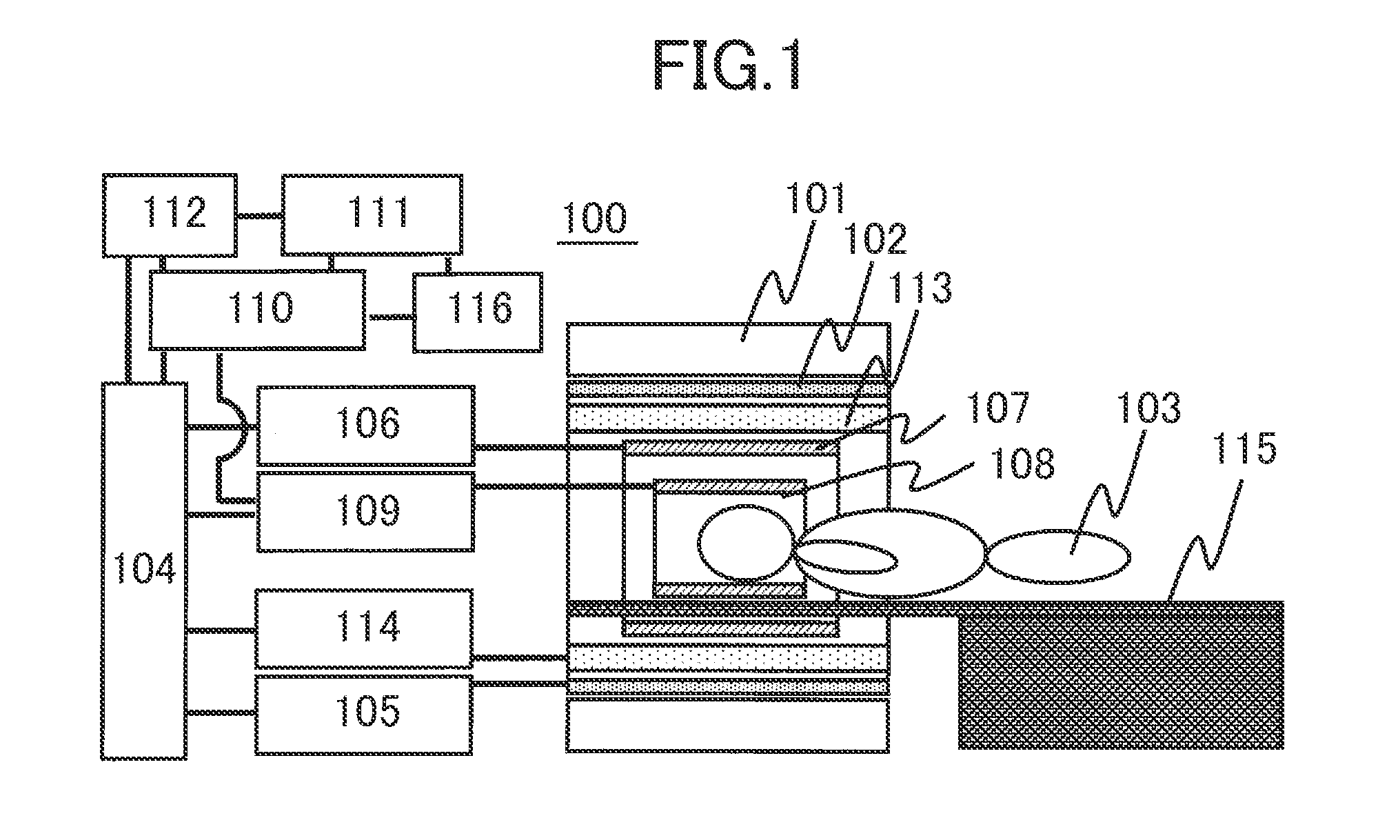
[0034]The embodiment of the present invention is described as below by way of an exemplary case where a magnetic resonance imaging (MRI) apparatus is used as the medical image acquisition apparatus while a medical diagnostic imaging support apparatus is incorporated in the MRI apparatus for medical image acquisition.
[0035]First, description is made on the magnetic resonance imaging (MRI) apparatus including the medical diagnostic imaging support apparatus according to the embodiment.
[0036]The MRI apparatus is a medical diagnostic imaging apparatus principally utilizing proton nuclear magnetic resonance phenomenon. The MRI apparatus is capable of non-invasive imaging of...
second embodiment
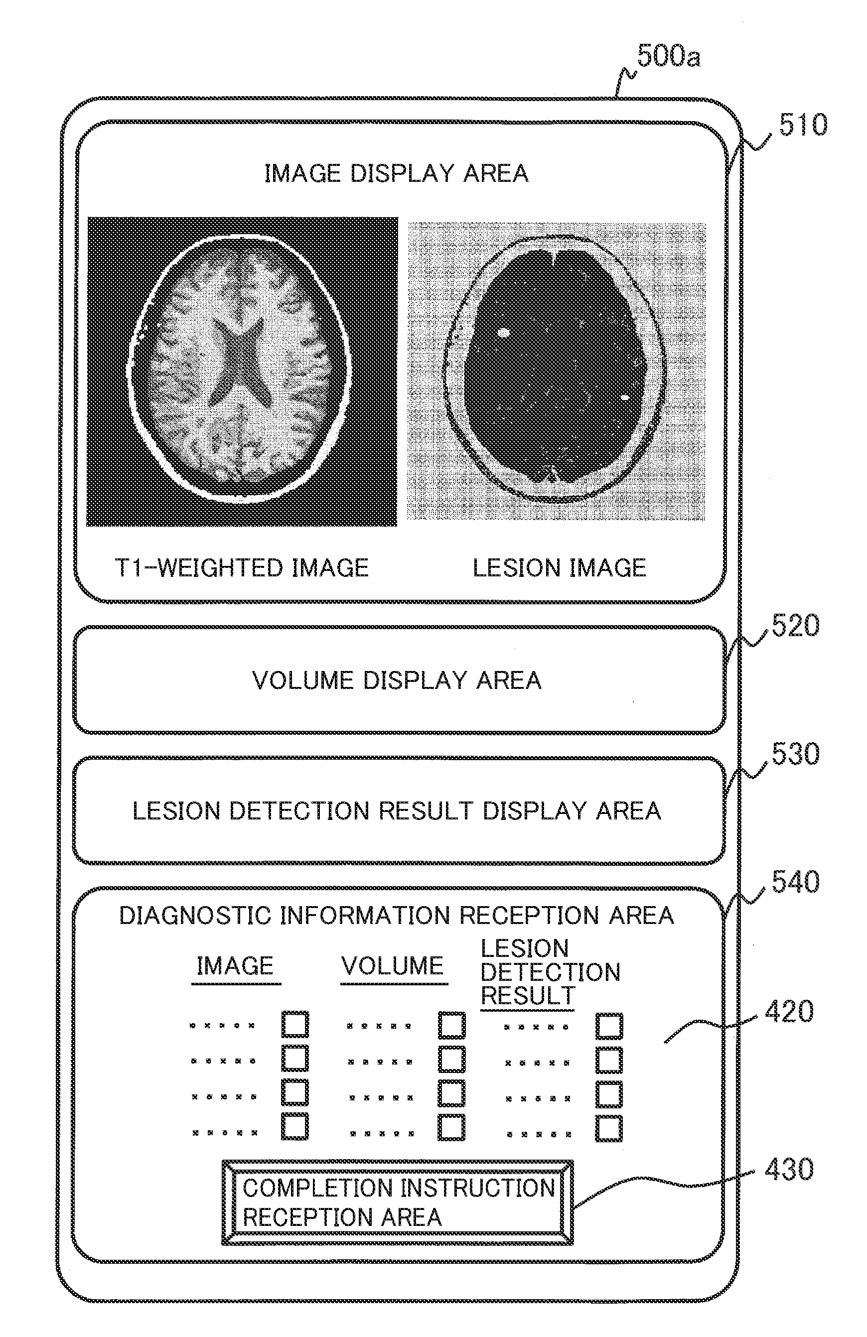
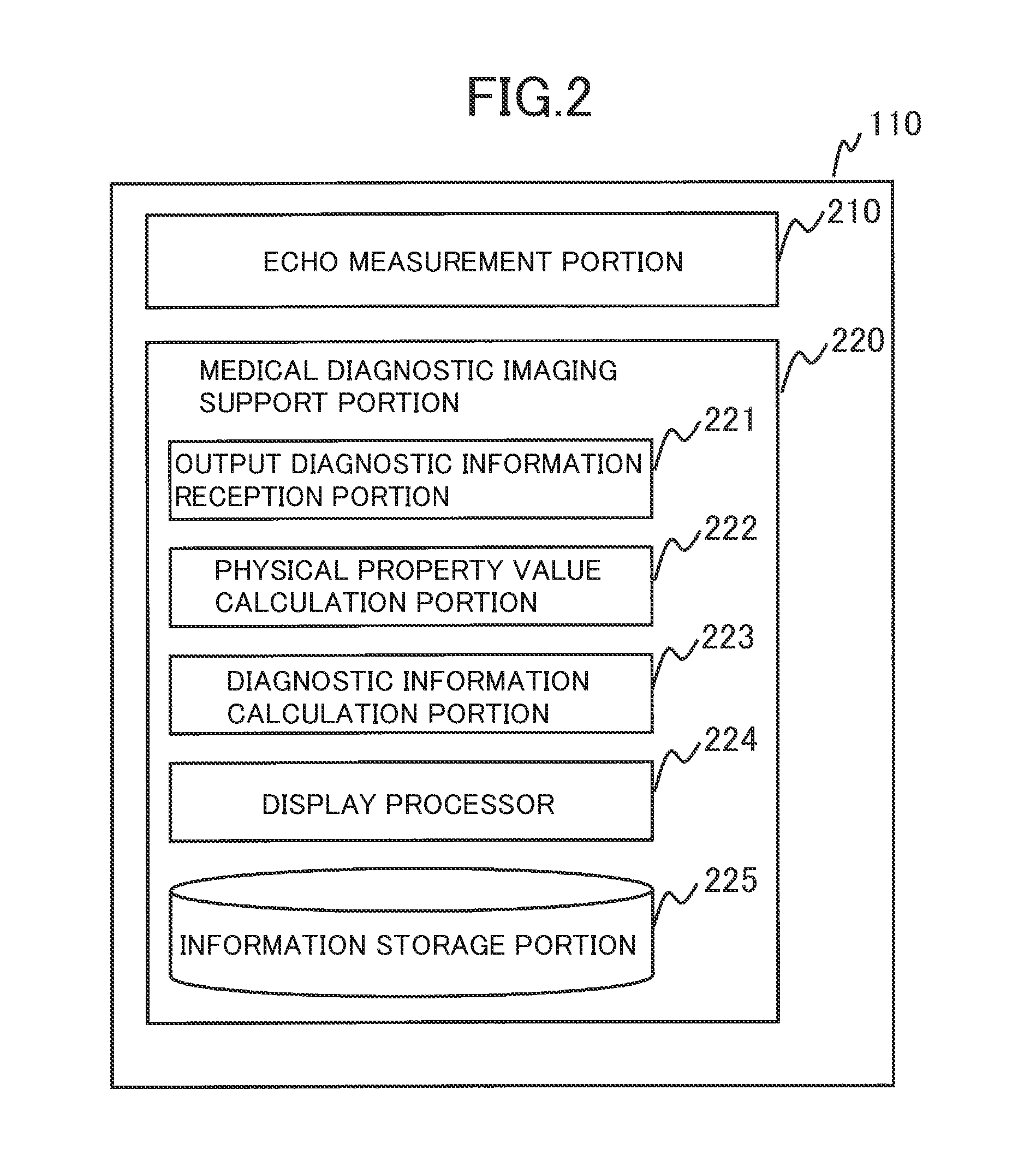
[0124]Next, description is made on a second embodiment of the present invention. According to this embodiment, the output information reception portion 211 has a function to receive the adjustment of the function and variable used for the calculation of the diagnostic information. Similarly to the first embodiment, the second embodiment is also described by way of example where the MRI apparatus is used as the medical image acquisition apparatus.
[0125]The MRI apparatus of this embodiment has basically the same configuration as the MRI apparatus 100 of the first embodiment. In order to implement the above function, however, a medical diagnostic imaging support portion 220a of this embodiment includes a calculation information adjustment portion 226 for adjusting the calculation information, as shown in FIG. 10. Further, an output diagnostic information reception screen 400b generated by an output diagnostic information reception portion 221a of this embodiment has a different configu...
third embodiment
[0151]Next, description is made on a third embodiment of the present invention. According to this embodiment, a pulse sequence capable of fastest acquisition of a physical property value necessary for input of user-specified diagnostic information is automatically generated.
[0152]An MRI apparatus of this embodiment has basically the same configuration as the MRI apparatus 100 of the first embodiment. In order to implement the above function, however, a medical diagnostic imaging support portion 220c of this embodiment has a different configuration. The following description is made, focusing on the difference from the first embodiment.
[0153]In order to accomplish the automatic generation of the pulse sequence, the medical diagnostic imaging support portion 220c of this embodiment includes an imaging planning portion 228 in addition to the components of the medical diagnostic imaging support portion 220 of the first embodiment, as shown in FIG. 13. Further, data stored in an informat...
PUM
 Abstract
Description
Claims
Application Information
 - R&D Engineer
- R&D Manager
- IP Professional
- Industry Leading Data Capabilities
- Powerful AI technology
- Patent DNA Extraction
Browse by: Latest US Patents, China's latest patents, Technical Efficacy Thesaurus, Application Domain, Technology Topic, Popular Technical Reports.
© 2024 PatSnap. All rights reserved.Legal|Privacy policy|Modern Slavery Act Transparency Statement|Sitemap|About US| Contact US: help@patsnap.com