
Pixel driving circuit, driving method thereof, and display device

a driving circuit and display device technology, applied in the field of display technology, can solve the problems of excessive working voltage of an oled, large voltage drop, and increase transient current and power consumption

Active Publication Date: 2017-01-19
BOE TECH GRP CO LTD +1
View PDF5 Cites 23 Cited by
  • Summary
  • Abstract
  • Description
  • Claims
  • Application Information

AI Technical Summary

Benefits of technology

The present invention provides a pixel driving circuit and a display device that can prevent flickering and voltage jump of an organic light-emitting diode caused by changes in data signals and electric leakage of a switching transistor. This is achieved by a threshold compensation unit and a voltage stabilizing unit that can stabilize a potential at a node to control the voltage output from the driving unit. The display device comprises this pixel driving circuit, which eliminates the problem of flicker.

Problems solved by technology

With an increase in display size, a traditional passive matrix OLED requires shorter driving time for a single pixel, which needs to increase transient current and power consumption.
In the meanwhile, large current will lead to an excessively large voltage drop on an ITO line and an excessively high working voltage of an OLED, so that efficiency of the OLED will be reduced.
If the threshold voltage Vthn of a pixel unit shifts over time, the current thereof may vary over time, which results in afterimage.
Moreover, different working voltages of the organic light-emitting diodes OLED due to non-uniformity of the organic light-emitting diodes OLED may also lead to different currents.
Nevertheless, the switching transistor TFT1 may still have a problem of electric leakage, which may cause a gate voltage of the driving transistor DTFT to vary when the data voltage changes, so that brightness of the organic light-emitting diode OLED changes over time, thereby resulting in flicker.

Method used


Image

  • Pixel driving circuit, driving method thereof, and display device
  • Pixel driving circuit, driving method thereof, and display device
  • Pixel driving circuit, driving method thereof, and display device

Examples


embodiment 1

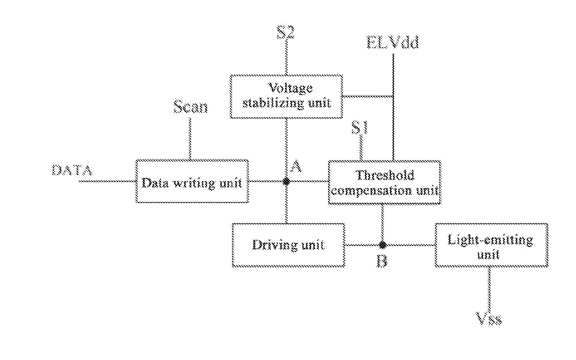
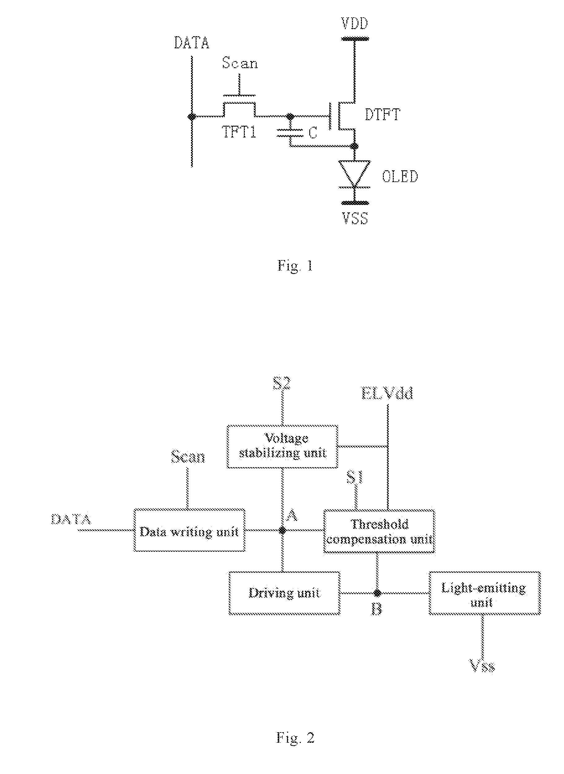
[0060]As shown in FIG. 2, this embodiment provides a pixel driving circuit, comprising a data writing unit, a threshold compensation unit, a driving unit, a light-emitting unit, and a voltage stabilizing unit; wherein, the data writing unit is connected with a first node A, a scan signal line Scan and a data signal line DATA, and is used for controlling whether to input a data signal inputted into the data signal line into the driving unit according to a scan signal inputted into the scan signal line Scan; the first node A is a connection node between the data writing unit and the driving unit; the threshold compensation unit is connected with the first node A, a first control signal line S1, a first voltage terminal ELVdd and the driving unit, and is used for compensating for a threshold voltage of the driving unit according to a first control signal inputted into the first control signal line S1; the driving unit is connected with the light-emitting unit, and is used for driving t...

embodiment 2

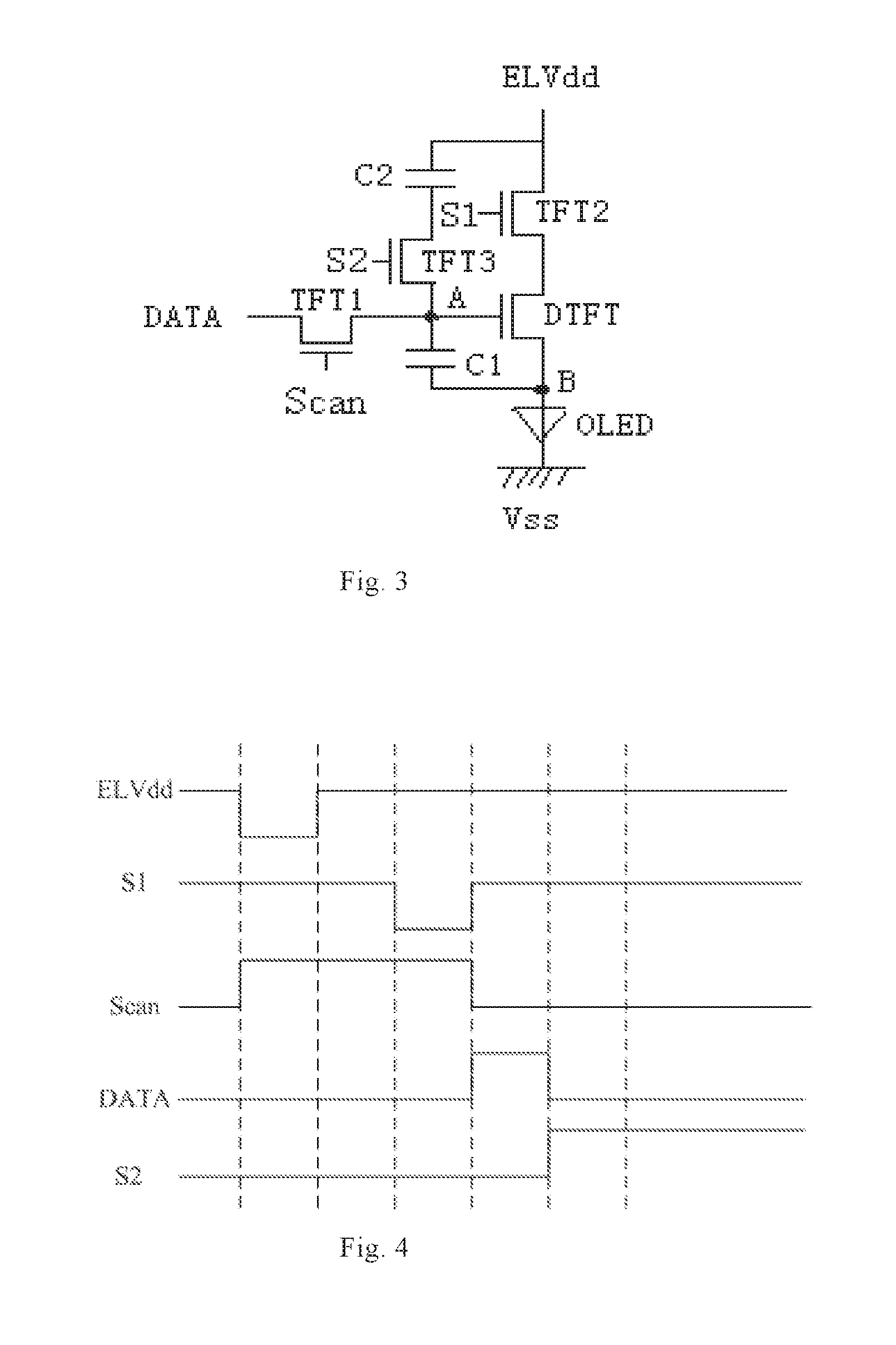
[0068]This embodiment provides a driving method of a pixel driving circuit, wherein the pixel driving circuit may be the pixel driving circuit provided in Embodiment 1. The specific driving method is described as follows.

[0069]The pixel driving circuit comprises a data writing unit, a threshold compensation unit, a driving unit, a light-emitting unit, and a voltage stabilizing unit; and the driving method comprises:

[0070]a reset stage: in which a reset signal is inputted, and the driving unit and the light-emitting unit are reset;

[0071]a threshold acquisition stage: in which a threshold acquisition signal is inputted into a first control signal line, a reference voltage signal is inputted into a data signal line, and a threshold voltage of the driving unit is acquired;

[0072]a data writing stage: in which a scan signal is inputted into a scan signal line Scan, the data signal inputted into the data signal line DATA and the threshold voltage are superimposed and written into the drivi...

embodiment 3

[0082]This embodiment also provides a pixel driving circuit, whose configuration is substantially the same as that in Embodiment 1, but differs in that the threshold compensation unit is further connected with a third control signal line. Specific configuration of the threshold compensation unit is different from that of the threshold compensation unit in Embodiment 1. The threshold compensation unit in this embodiment comprises a second transistor, a fourth transistor TFT4, a first storage capacitor and a third storage capacitor C3. Connection relations in the pixel driving circuit in this embodiment are specifically described as follows.

[0083]As shown in FIG. 5, the data writing unit comprises a first transistor TFT1; the threshold compensation unit comprises a second transistor TFT2, a fourth transistor TFT4, a first storage capacitor C1 and a third storage capacitor C3; the light-emitting unit is an organic light-emitting diode OLED; the voltage stabilizing unit comprises a thir...


PUM


Abstract

The present invention provides a pixel driving circuit, a driving method thereof, and a display device. The pixel driving circuit of the present invention comprises a data writing unit, a threshold compensation unit, a driving unit, a light-emitting unit, and a voltage stabilizing unit; the data writing unit is connected with a first node, a scan signal line and a data signal line; the first node is a connection node between the data writing unit and the driving unit; the threshold compensation unit is connected with the first node, a first control signal line, a first voltage terminal and the driving unit; the driving unit is connected with the light-emitting unit; and the voltage stabilizing unit is connected with the data writing unit, a second control signal line and the first voltage terminal.

Description

CROSS REFERENCE TO RELATED APPLICATION[0001]The present application claims the benefit of Chinese Patent Application No. 201510427812.9 filed on Jul. 17, 2015 in China, the entire contents of which are herein incorporated by reference.FIELD OF THE INVENTION[0002]The present invention belongs to the field of display technology, and particularly relates to a pixel driving circuit, a driving method thereof, and a display device.BACKGROUND OF THE INVENTION[0003]Organic light-emitting diodes (OLEDs), as current mode light-emitting diodes, have been more and more applied to high-performance display. With an increase in display size, a traditional passive matrix OLED requires shorter driving time for a single pixel, which needs to increase transient current and power consumption. In the meanwhile, large current will lead to an excessively large voltage drop on an ITO line and an excessively high working voltage of an OLED, so that efficiency of the OLED will be reduced. However, such probl...

Claims


Application Information

Patent Timeline
Patent Type & Authority Applications(United States)
IPC IPC(8): G09G3/3258G09G3/3266
CPCG09G3/3258G09G2300/0852G09G2320/0247G09G3/3266G09G3/3233G09G2300/0819G09G2300/0861G09G2300/0866
Inventor ZHANG, YUTINGLIAO, FENGWU, ZHONGYUANXU, PAN
Owner BOE TECH GRP CO LTD
Features
  • Generate Ideas
  • Intellectual Property
  • Life Sciences
  • Materials
  • Tech Scout
  • Unparalleled Data Quality
  • Higher Quality Content
  • 60% Fewer Hallucinations
Learn More