Intermittent urinary catheter
a urinary catheter and catheter technology, applied in the field of medical devices, can solve the problems of inadvertent catheter advance, inability to fully drain the bladder,
- Summary
- Abstract
- Description
- Claims
- Application Information
AI Technical Summary
Benefits of technology
Problems solved by technology
Method used
Image
Examples
second embodiment
[0083]With primary reference to FIGS. 7A-9B, catheter 30B is shown having a bulbous or truncated teardrop-shaped head 56 formed in the first end 32 of the catheter sidewall 36. The truncated teardrop-shaped head 56 extends radially outwardly from longitudinal axis X to provide a second outer diameter OD2 that is larger than the outer diameter OD1 of sidewall 36. Outer surface 40 extends continuously along truncated teardrop-shaped head 56 having a first sloped surface 40A, an apex surface 40B, a second sloped surface 40C, and a sidewall surface 40D when viewed from the side. As seen in FIG. 7B, first sloped surface 40A extends a distance from rounded end wall 32A flared radially outward from axis X towards second end 34. Apex surface 40B is positioned below first sloped surface 40A when device 30B is oriented vertically. Apex surface 40B forms an apex from which the outer diameter OD2 of head 56 is determined. Second sloped surface 40C extends a distance from apex surface 40B flared...
third embodiment
[0085]With primary reference to FIGS. 10A-10C, the third embodiment catheter 30C has a plurality of convexly-shaped dimples 60 along outer surface 40, a plurality of concavely-shaped dimples 62 along inner surface 42, a plurality outer surface retention areas 43, a first outer diameter OD1, a second outer diameter OD3, first inner diameter ID5, second inner diameter ID6, in addition to other elements having similar reference numerals as the other embodiments. Catheter 30C may have a generally non-circular cross section or textured outer surface 40 and a generally non-circular cross section or textured inner surface 42. Convex dimples 60 are formed along the outer surface 40 in the catheter sidewall 36. The term convex with respect to dimples 60 refers to the dimples extending radially out of the catheter sidewall 36 and the dimple surface facing outward as viewed from above as seen in FIG. 10A. Convex dimples 60 have an outer annular edge 60A and an apex 60B. Annular edge 60A is a g...
embodiment 30b
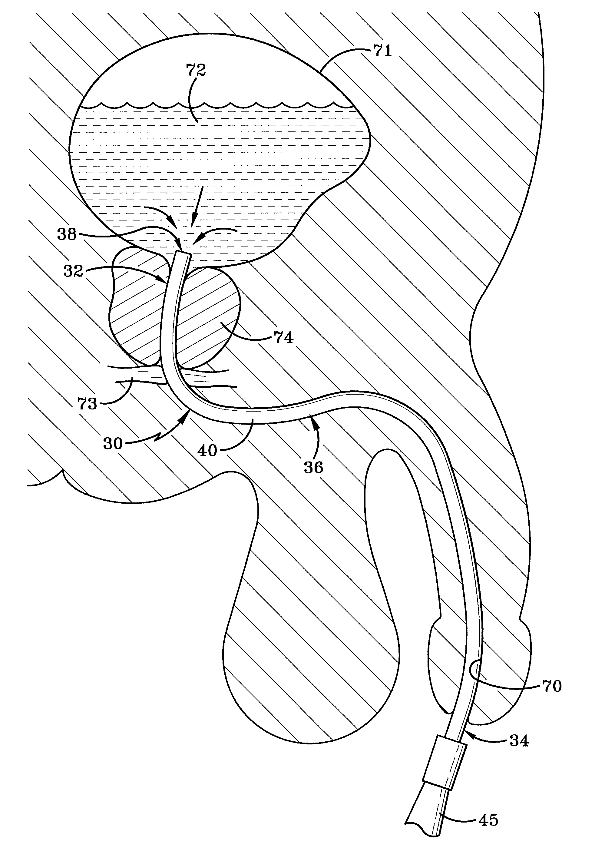
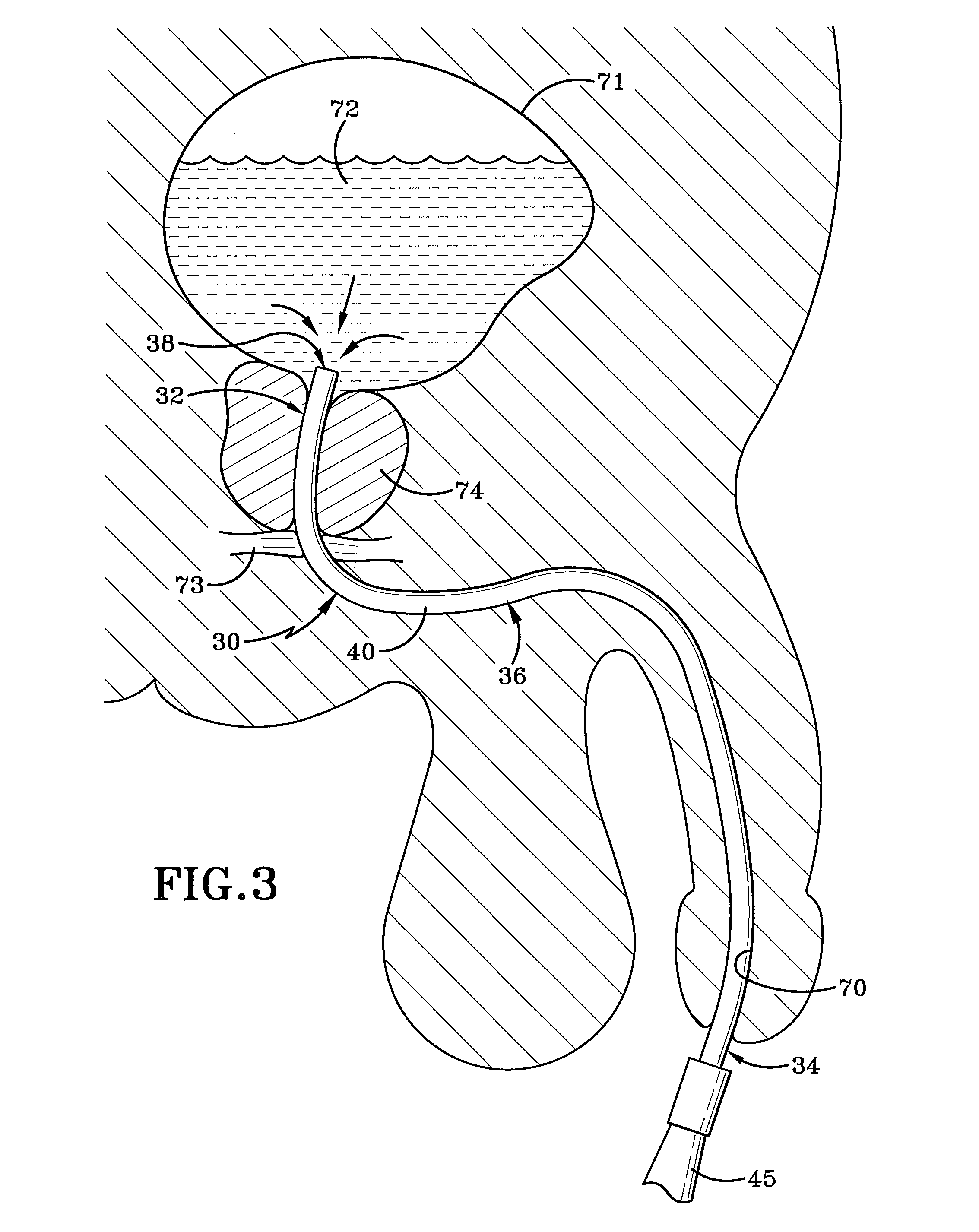
[0131]Alternative embodiment 30B of the present disclosure operates by first aligning truncated tear drop head 56 with urethral canal 70, then inserting head 56 into the urethral canal 70. The head 56 outer diameter OD2 is generally equal to or slightly larger than the upstretched diameter of the urethral canal 70. Catheter 30B is manipulated so the truncated tear drop head 56 advances through the urethral canal 70 until it is in communication with the bladder 71. The head 56 operates as a guide to navigate the natural curvature often found in the urethral canal 70 of males.
PUM
 Abstract
Description
Claims
Application Information
 - R&D
- Intellectual Property
- Life Sciences
- Materials
- Tech Scout
- Unparalleled Data Quality
- Higher Quality Content
- 60% Fewer Hallucinations
Browse by: Latest US Patents, China's latest patents, Technical Efficacy Thesaurus, Application Domain, Technology Topic, Popular Technical Reports.
© 2025 PatSnap. All rights reserved.Legal|Privacy policy|Modern Slavery Act Transparency Statement|Sitemap|About US| Contact US: help@patsnap.com


