Internal combustion engine

a combustion engine and combustion chamber technology, applied in the direction of liquid fuel engines, auxilary lubrication, non-mechanical valves, etc., can solve the problem and achieve the effect of reducing the noise of combustion air

Active Publication Date: 2017-01-26
TOYOTA JIDOSHA KK
View PDF6 Cites 1 Cited by
  • Summary
  • Abstract
  • Description
  • Claims
  • Application Information

AI Technical Summary

Problems solved by technology

The discharging noise of ...

Method used


Image

  • Internal combustion engine
  • Internal combustion engine
  • Internal combustion engine

Examples


Embodiment Construction

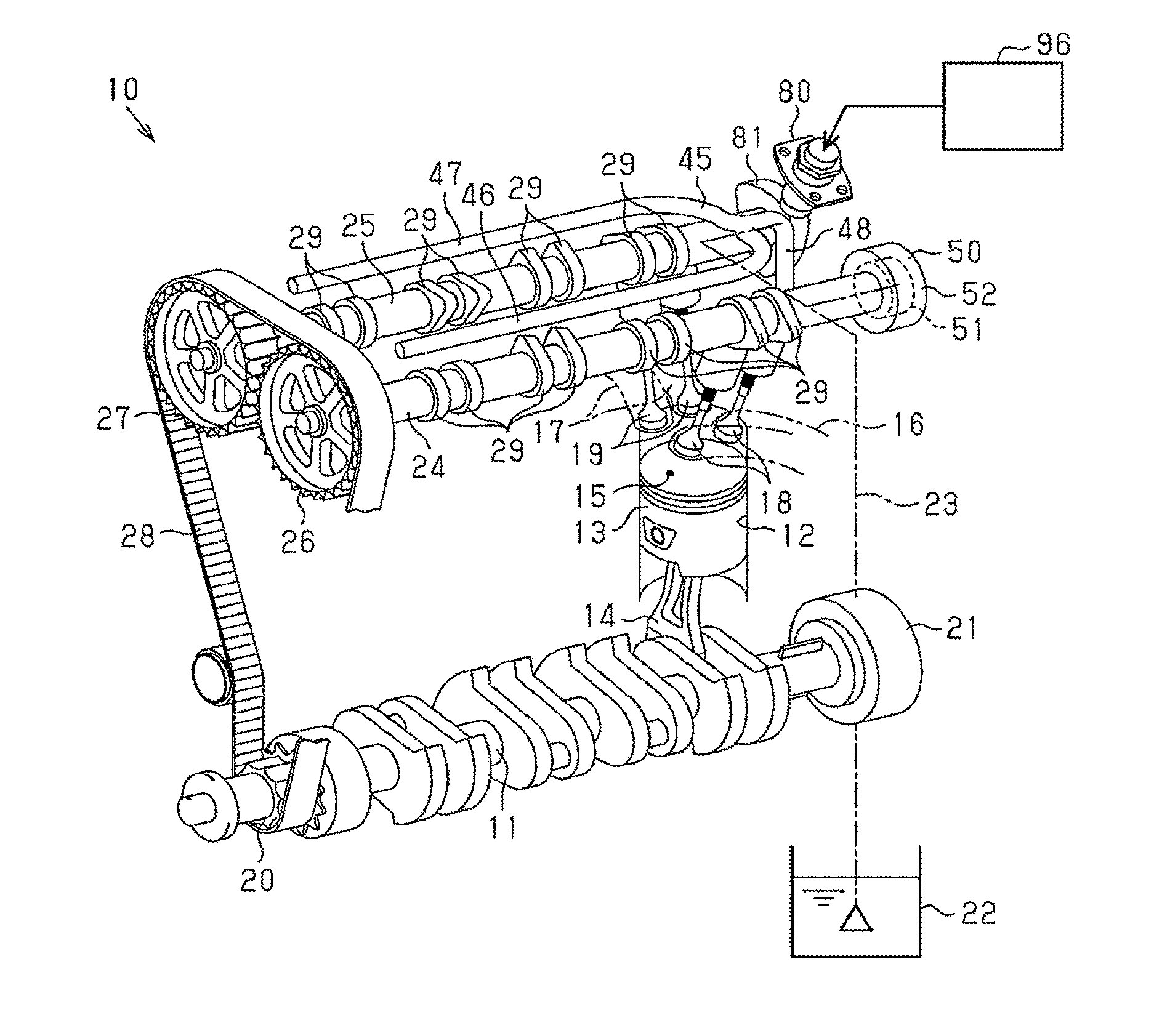
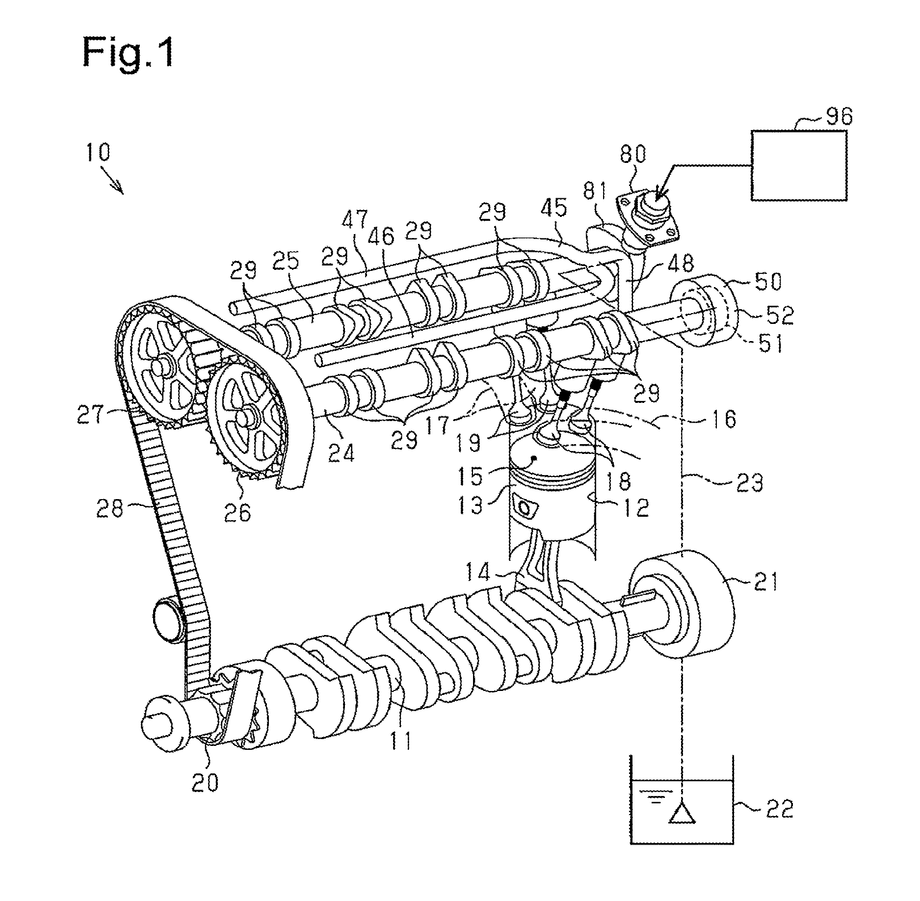
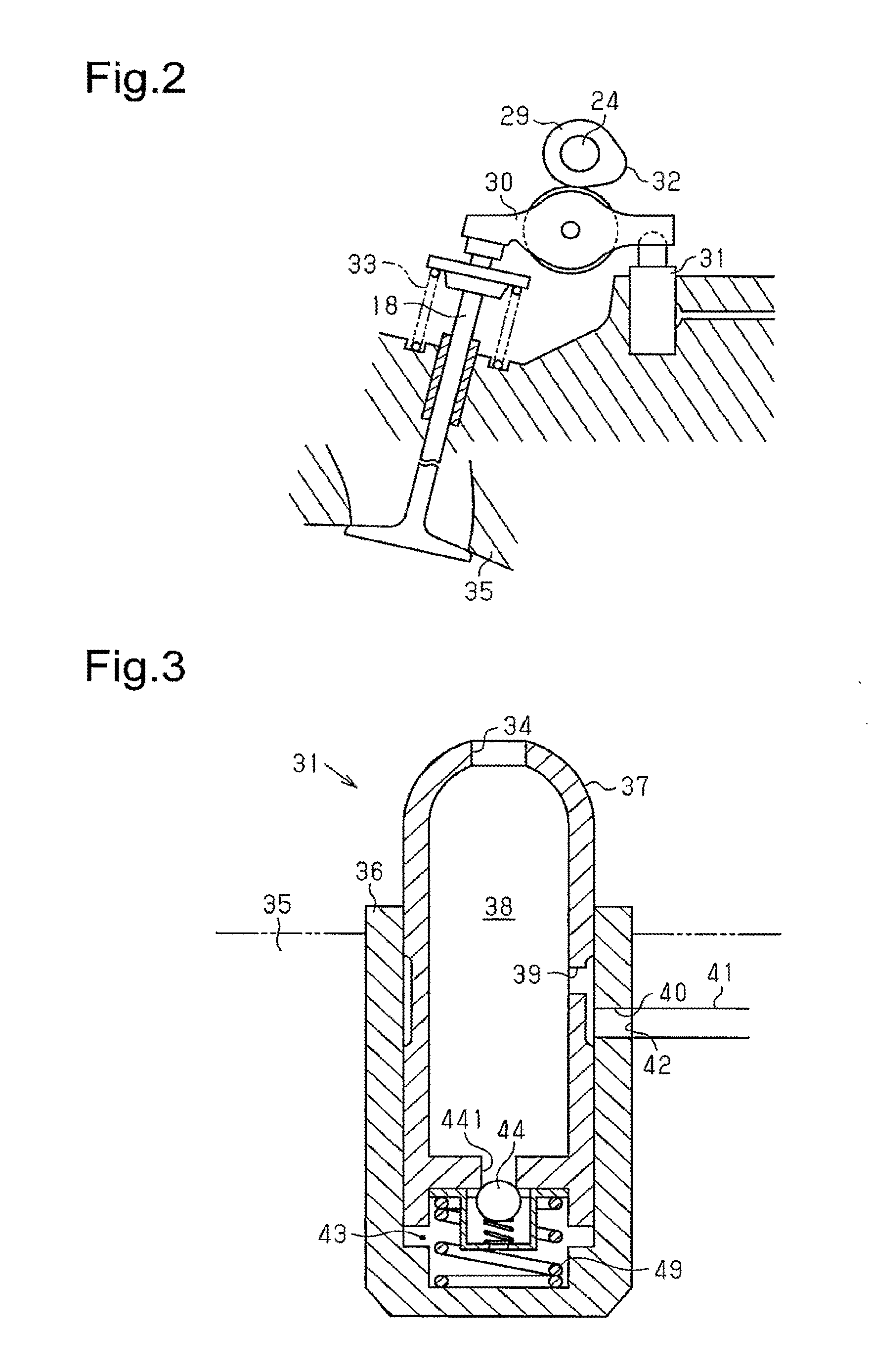
[0029]One embodiment of an internal combustion engine will be described below with reference to FIGS. 1 to 12. In the present embodiment, an in-line four cylinder internal combustion engine will be described by way of example.

[0030]As shown in FIG. 1, a piston 13 is connected to a crankshaft 11 of an internal combustion engine 10 by way of a connecting rod 14. A cylinder 12 and a combustion chamber 15 are formed in a cylinder block of the internal combustion engine 10. The piston 13 is arranged to reciprocate in the cylinder 12. The combustion chamber 15 is formed by a top surface of the piston 13 and wall surfaces of the cylinder 12 and a cylinder head. An intake passage 16 and an exhaust passage 17 are connected to the combustion chamber 15. The intake passage 16 and the exhaust passage 17 are respectively connected to the combustion chamber 15 while being divided to two ways. An intake valve 18 is arranged at a connecting portion of the intake passage 16 and the combustion chambe...


PUM


Abstract

An internal combustion engine includes an intake camshaft, a vacuum pump, an oil pump, and an oil feeding passage serving as an oil supplying path. The vacuum pump includes a rotor and a housing. The vacuum pump is formed with a negative pressure chamber that generates a negative pressure, and an oil path connected to the negative pressure chamber. An atmosphere communication hole for supplying air to the negative pressure chamber through the oil feeding passage and the oil path when the vacuum pump is stopped is arranged in the oil feeding passage. The atmosphere communication hole communicates the negative pressure chamber and the atmosphere before an amount of oil in the housing exceeds an allowable oil amount when the vacuum pump is stopped.

Description

BACKGROUND OF THE INVENTION[0001]The present invention relates to an internal combustion engine including a vacuum pump.[0002]Japanese Laid-Open Patent Publication No. 2006-118424, for example, discloses a conventional internal combustion engine including a vacuum pump that generates a negative pressure.[0003]As shown in FIG. 16, a vacuum pump 200 disclosed in Japanese Laid-Open Patent Publication No. 2006-118424 includes a rotor 202, and a housing 203 that accommodates the rotor 202. The rotor 202 is coupled to a camshaft 201 to integrally rotate with the camshaft 201. The housing 203 rotatably supports the rotor 202.[0004]As shown in FIG. 17, a plurality of vanes 204 is attached to the rotor 202 to be slidable in a radial direction of the rotor 202. The plurality of vanes 204 partitions the interior of the housing 203 into a plurality of spaces. A center axis of the rotor 202 is arranged to be decentered with respect to a center axis of the housing 203. Thus, when the rotor 202 is...

Claims


Application Information

Patent Timeline
IPC IPC(8): F01L9/02F02M59/44F01L1/18F01L1/047F01L1/24F01L9/16
CPCF01L9/026F01L1/047F01L2001/2444F01L1/18F02M59/44F01L1/24F01L1/255F01L1/348F01M1/02F01M1/06F01M9/08F02M37/043F04C18/3446F04C29/025F01M2001/064F01L1/053F01L1/185F01L1/2405F01L1/46F01L2001/0537F01L2250/04F01L2810/02B60T17/02F02B63/06F02B67/04F01M9/10F01L2305/00F01L9/16
Inventor HARA, HIROKI
Owner TOYOTA JIDOSHA KK
Why Eureka
Try Eureka