Adaptive positioning system

a positioning system and positioning system technology, applied in the field of estimation of the position of objects, can solve the problems of inability to completely overcome the limitations of most individual sensors, inability to offer systematic means to adapt behavior, and inability to completely overcome data, etc., to achieve dramatic improvements in positioning, reduce odometric drift and error, and accurate positioning results

Inactive Publication Date: 2017-01-26
HUMATICS CORP
View PDF3 Cites 81 Cited by
  • Summary
  • Abstract
  • Description
  • Claims
  • Application Information

AI Technical Summary

Benefits of technology

[0022]URDIS allows the APS system to reference organic, ubiquitous features in the world either as a priori contextual backdrops or as recent local-environment representations that can be used to reduce odometric drift and error until the next active landmark (i.e. another UWB module) can be located. Even if no other active landmark is identified, the use of URDIS and other UWB-radar systems offer the potential for dramatic improvements in positioning.
[0023]This method combines the benefits of a stereo-vision system with the benefits of LiDAR, but with the added advantage that because it uses UWB signals, it does not have line-of-sight limitations. This differentiates the current invention from strategies employing cameras or LiDAR because the latter are limited to line-of-sight measurements. With cameras and LiDAR, obstacles such as crowds of people, snow drifts, stacks of palettes, etc., obscure the view of would-be environmental landmarks and features. Worse, cameras and LiDAR are further limited by naturally-occurring obscurants such as rain, snow, fog and even vegetation.
[0024]Traditional approaches that try to match the current view of the environment to a pre-made map can be easily rendered useless by these obstacles / obscurants, but the proposed method of using a UWB Radar depth image allows APS to reference a much broader range of features and to locate these features even within cluttered and dynamic areas. By using UWB P2P ranging together with UWB depth-radar ranging, APS is able to leverage the benefits of active landmarks at known positions while at the same time producing accurate positioning results over long stretches in between those known landmarks by using UWB radar to positively fix organic, readily available features, all without the need for infrastructure changes to the environment.

Problems solved by technology

Most individual sensors have limitations that cannot be completely overcome.
The APS creates a modular framework in which the sensor data is fully utilized when it is healthy, but that data is ignored or decremented in importance when it is not found to be accurate or reliable.
Current approaches do not offer a systematic means to adapt behavior in response to positioning requirements and / or contingencies.

Method used


Image

  • Adaptive positioning system
  • Adaptive positioning system
  • Adaptive positioning system

Examples


Embodiment Construction

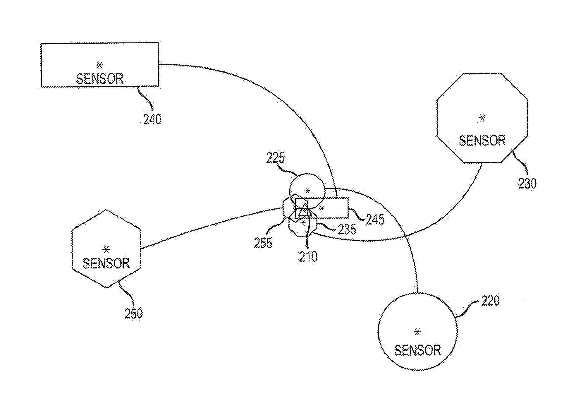
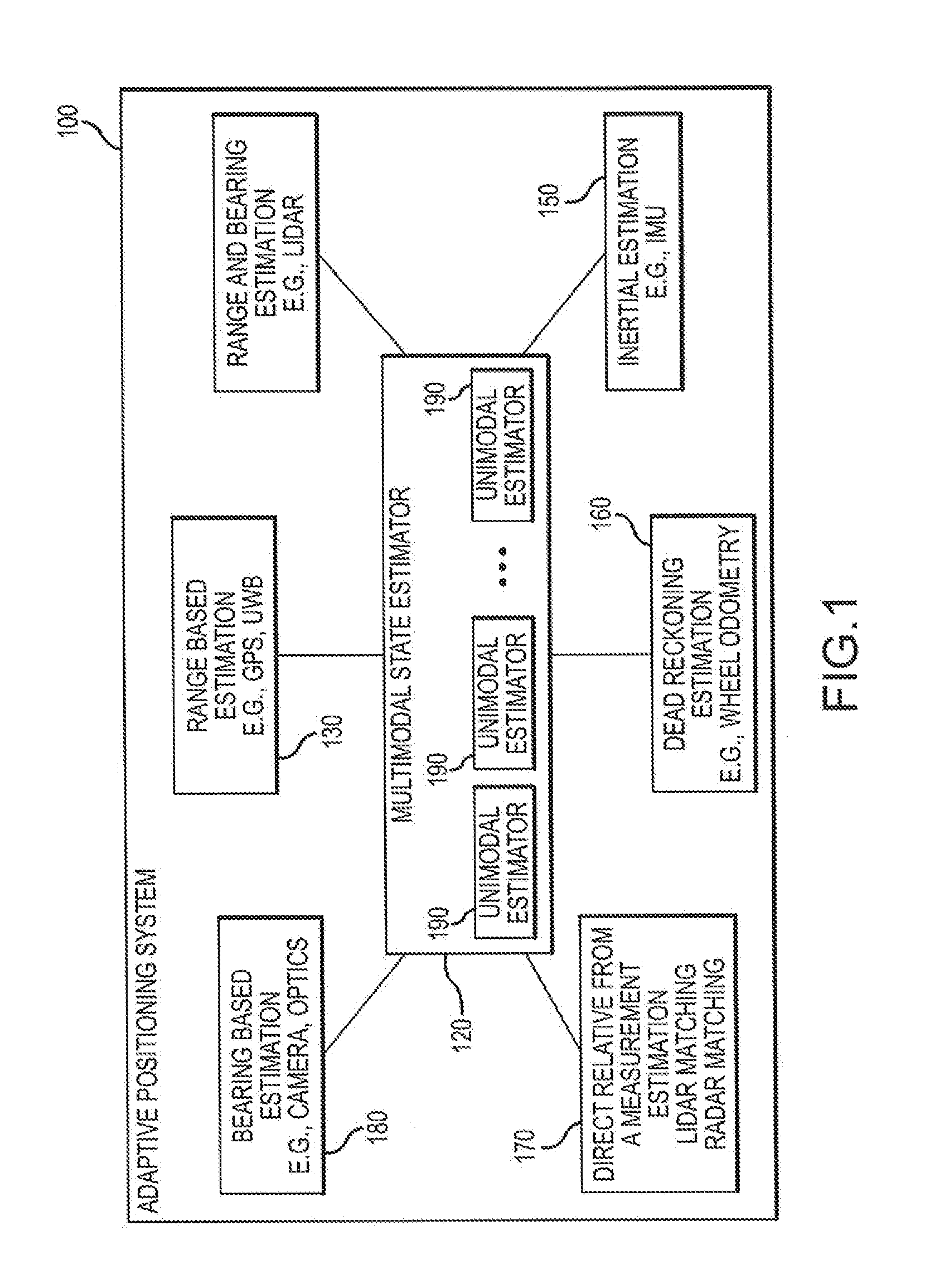
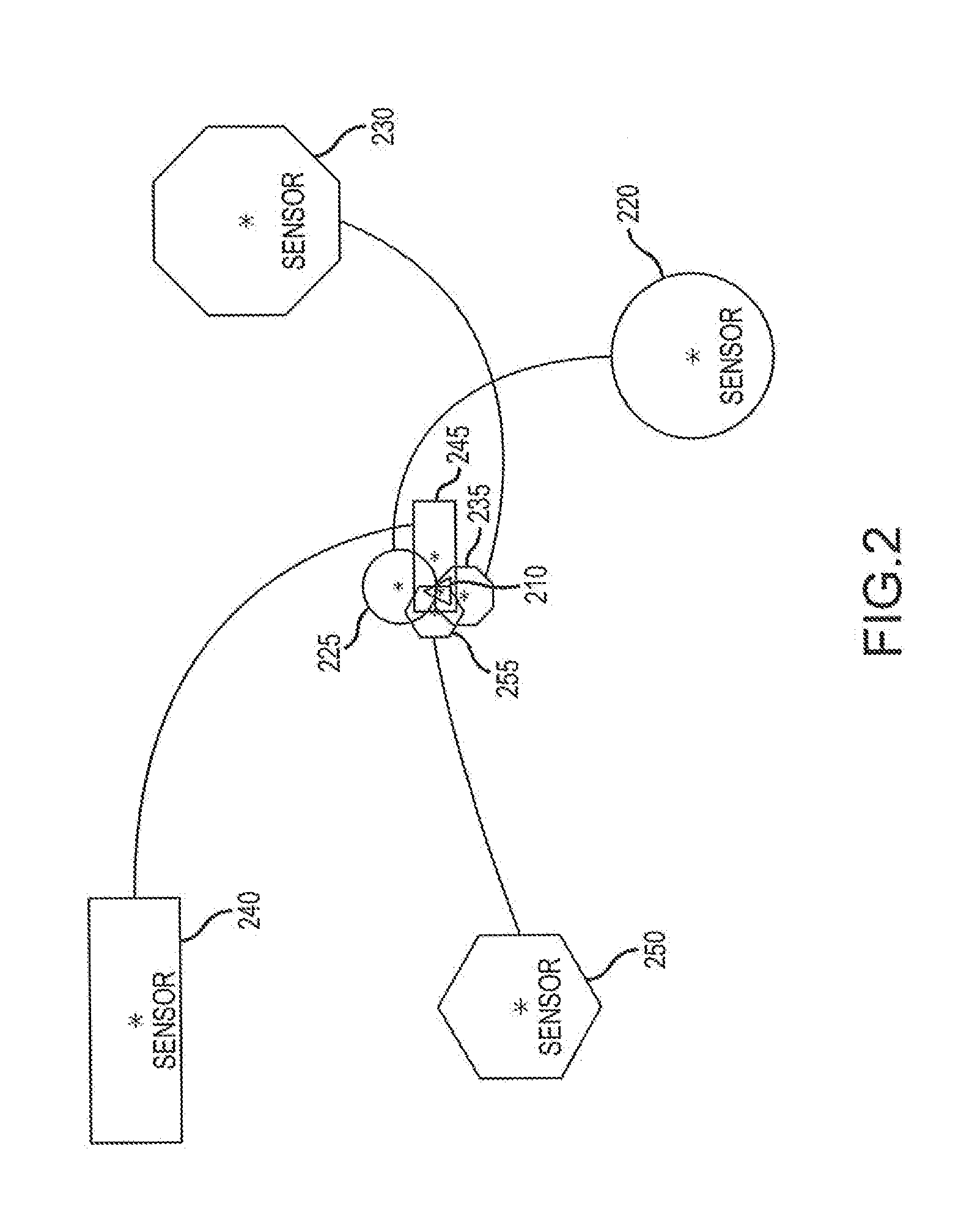
[0040]An Adaptive Positioning System (APS) synthesizes a plurality of positioning systems by employing a variety of different, complementary methods and sensor types to estimate the position of the object while at the same time assessing the health / performance of each of the various sensors providing positioning data. All positioning sensors have particular failure modes or certain inherent limitations which render their determination of a particular position incorrect. However, these failure modes and limitations can be neither completely mitigated nor predicted. The various embodiments of the present invention provide a way to mitigate sensor failure through use of an adaptive positioning method that iteratively evaluates the current effectiveness of each sensor / technique by comparing its contribution to those of other sensors / techniques currently available to the system.

[0041]The APS of the present invention creates a modular framework in which the sensor data from each sensor sy...


PUM


Abstract

An Adaptive Positioning System provides a method for directing and tracking position, motion and orientation of mobile vehicles, people and other entities using multiple complementary positioning components to provide seamless positioning and behavior across a spectrum of indoor and outdoor environments. The Adaptive Positioning System (APS) provides for complementary use of peer to peer ranging together with map matching to alleviate the need for active tags throughout an environment. Moreover, the APS evaluates the validity and improves the effective accuracy of each sensor by comparing each sensor to a collaborative model of the positional environment. The APS is applicable for use with multiple sensors on a single entity (i.e. a single robot) or across multiple entities (i.e. multiple robots) and even types of entities (i.e. robots, humans, cell phones, cars, trucks, drones, etc.).

Description

RELATED APPLICATION[0001]The present application relates to and claims the benefit of priority to United States Provisional Patent Applications no. 62 / 158,940 filed 8 May 2015, 62 / 332,234 filed 5 May 2016, and 62 / 333,128 filed 6 May 2016 which are hereby incorporated by reference in their entirety for all purposes as if fully set forth herein.BACKGROUND OF THE INVENTION[0002]Field of the Invention[0003]Embodiments of the present invention relate, in general, to estimation of an object's position and more particularly to the application of multimodal positional estimation with behavior modification to optimize positional estimation of an object.[0004]Relevant Background[0005]Service providers of all types have begun to recognize that positioning services (i.e., services that identify the position of an object, wireless terminal or the like) may be used in various applications to provide value-added features. A service provider may also use positioning services to provide position-sen...

Claims


Application Information

Patent Timeline
Patent Type & Authority Applications(United States)
IPC IPC(8): G01S5/02
CPCG01S5/0252G01S5/0263G01S5/0278G01S17/86G01S17/931G06V40/20G06V10/20G01C21/005G01S5/0244G01C21/3837G01S19/00G06F11/30G07C5/00
Inventor BRUEMMER, DAVID J.SENNA, JOSHJAIN, AKSHAY KUMARATHERTON, J ALANROHR, DAVID
Owner HUMATICS CORP
Why Eureka
Try Eureka