Wireless Charger

a charging device and wireless technology, applied in the direction of charging devices, charging devices, charging data, etc., can solve the problems that the unique dc interface of the charging cord/station cannot be used with any other portable devices on the market, cannot solve the problem completely, and only the use of the particular devi

Active Publication Date: 2017-01-26
PASS SEYMOUR
View PDF7 Cites 40 Cited by
  • Summary
  • Abstract
  • Description
  • Claims
  • Application Information

AI Technical Summary

Benefits of technology

[0010]The present invention addresses the needs described above by providing a wireless charger that addresses the issues described above. Accordingly, the wireless charger of the present invention may be realized in a wiring device form factor that provides the user with wireless charging capabilities while s

Problems solved by technology

One drawback to this approach is that the charging cord/station is only usable with that particular device.
Thus, its unique DC interface cannot be used with any of the other portable devices on the market because they have charging receptacles with a different form factor.
As a result, when one of the charging station or the portable device gets damaged or has reached end of life, both have to be replaced.
While this approach goes a long way toward solving the universality issue, it does not totally solve the problem; the so-called standardized low voltage ports actually comprise a family of low voltage port standards.
One drawback to this approach therefore relates to the user's accumulation of low voltage cords over time.
As a result, these charger types are susceptible to being

Method used


Image

  • Wireless Charger
  • Wireless Charger
  • Wireless Charger

Examples


Embodiment Construction

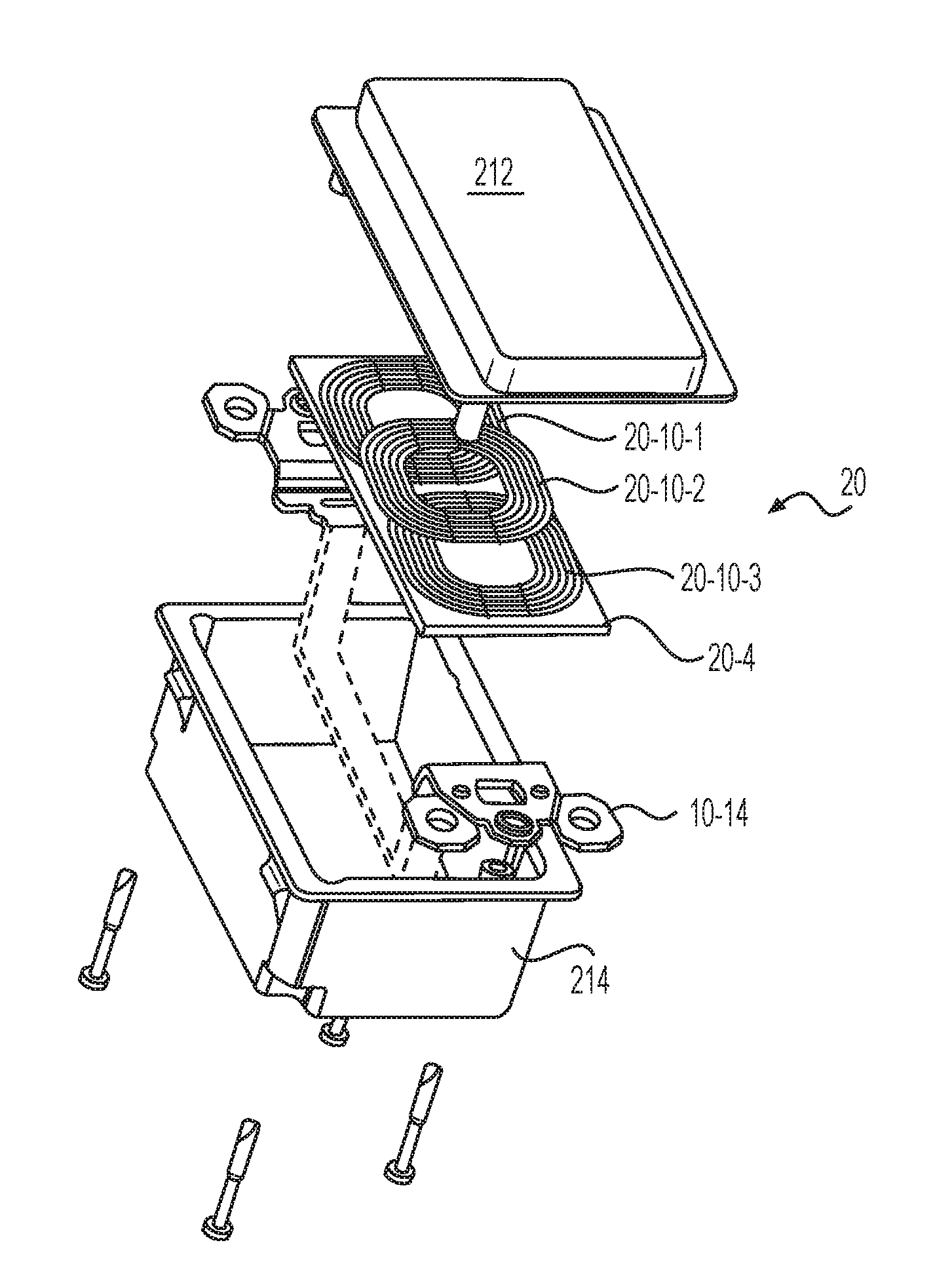
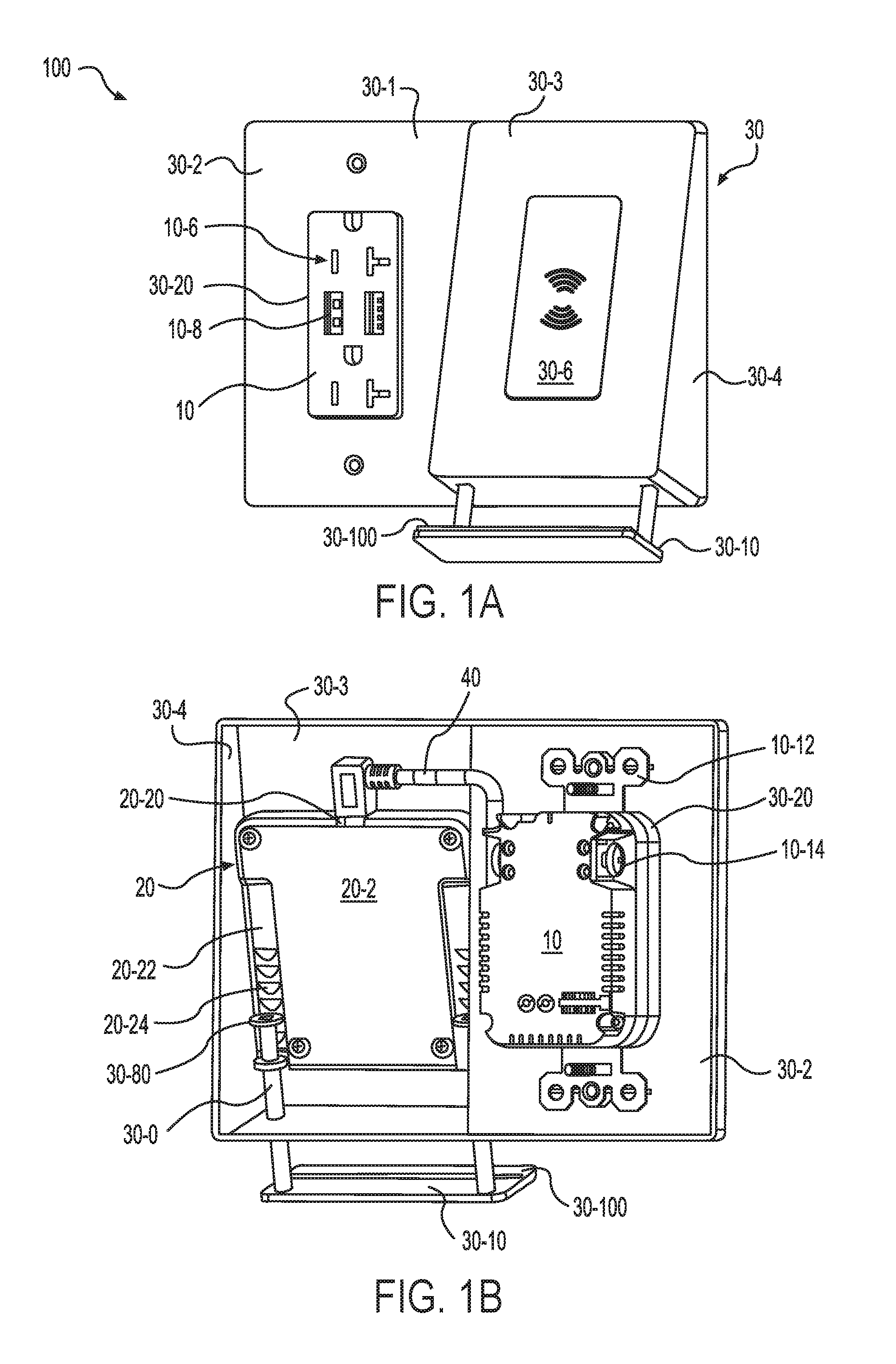
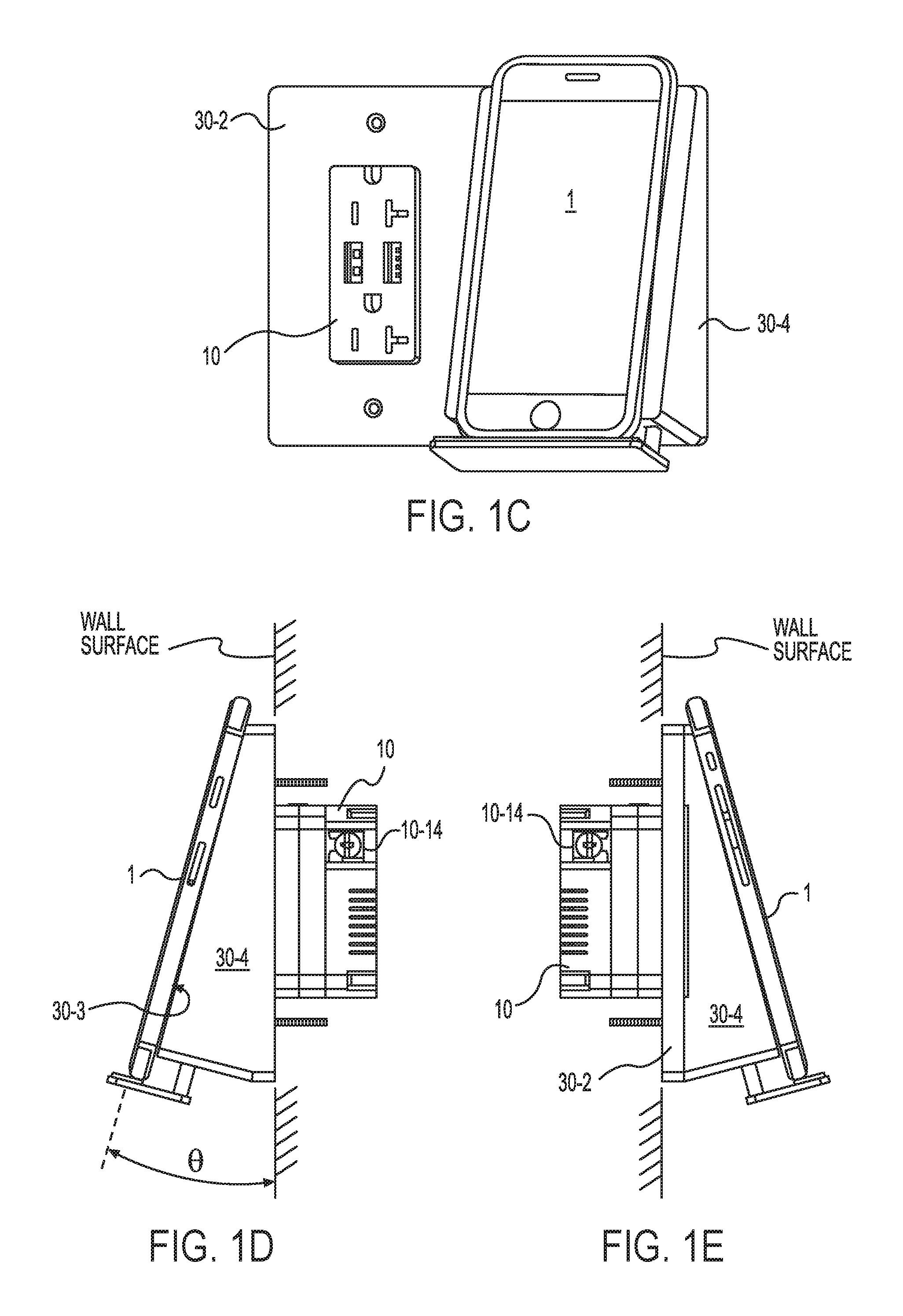
[0133]Reference will now be made in detail to the present exemplary embodiments of the invention, examples of which are illustrated in the accompanying drawings. Wherever possible, the same reference numbers will be used throughout the drawings to refer to the same or like parts. An exemplary embodiment of the electrical assembly of the present invention is shown in FIG. 1A, and is designated generally throughout by reference numeral 100.

[0134]In accordance with the invention, the present invention for an electrical wiring assembly 100 may include an electrical wiring device 10 that is configured to be mounted to a device box. A set of electrical terminals 10-14 are at least partially disposed in the device housing configured for connection to AC distribution wires in the device box. The assembly includes a wall plate assembly 30, a wall plate housing assembly 300 or a wall box assembly 300 that is configured to accommodate the electrical wiring device 10. The wall plate assembly 30...


PUM


Abstract

The present invention is directed to an electrical wiring assembly that includes a plurality of line terminals configured to be coupled to a source of AC power. A circuit assembly is coupled to the plurality of line terminals. The circuit assembly includes a control circuit coupled to at least one electro-magnetic coil, the control circuit being configured to provide an electrical drive signal to the at least one electro-magnetic coil in accordance with a predetermined wireless charging regimen. The at least one electro-magnetic coil is configured to propagate a magnetic field in accordance with the electrical drive signal. A wall plate assembly is configured to accommodate the circuit assembly therewithin, the wall plate assembly including a charging interface region configured to accommodate a portable electronic device. The charging interface region is configured to position the at least one electro-magnetic coil proximate the portable electronic device so that the portable electronic device is disposed within the propagated magnetic field in accordance with the predetermined wireless charging regimen.

Description

CROSS-REFERENCE TO RELATED APPLICATIONS[0001]This application claims priority to U.S. Provisional Patent Application Ser. No. 62 / 171,479 filed on Jun. 5, 2015, the content of which is relied upon and incorporated herein by reference in its entirety, and the benefit of priority under 35 U.S.C. §119(e) is hereby claimed.BACKGROUND OF THE INVENTION[0002]1. Field of the Invention[0003]The present invention relates generally to charging devices, and particularly to wireless charging devices.[0004]2. Technical Background[0005]Portable or hand-held electronic devices have become ubiquitous. Moreover, the communications and computing technology spaces over-lap with modern cell phones and lap-tops, tablets and I-pads having much of the same. One reason that these devices are so popular relates to the fact that they can be carried and used by the user almost anywhere. Thus, a user can make telephone calls, send and receive emails, exchange text messages and / or browse the internet on the fly. ...

Claims


Application Information

Patent Timeline
IPC IPC(8): H02J7/02H01R25/00H02J50/20H02J50/12H02J50/10
CPCH02J7/025H02J50/12H01R25/006H02J50/20H02J50/10H02J7/0044H02J7/0049H02J7/00034H02G3/14H02J50/00
Inventor ROHMER, RICHARD M.MUELLER, BRIANROY, THOMAS F.
Owner PASS SEYMOUR
Why Eureka
Try Eureka