Intramedullary implants for replacing lost bone

a technology of intramedullary implants and bone, which is applied in the direction of internal osteosythesis, osteosynthesis devices, fasteners, etc., can solve the problems of infected sections, segmental defects, and need to be removed

Active Publication Date: 2017-02-09
NUVASIVE SPECIALIZED ORTHOPEDICS INC
View PDF0 Cites 3 Cited by
  • Summary
  • Abstract
  • Description
  • Claims
  • Application Information

AI Technical Summary

Benefits of technology

The patent describes an implantable dynamic apparatus that includes a nail and a magnetic assembly. The nail has two parts that can move relative to each other. The second part of the nail has internal threads, while the magnetic assembly has external threads that fit with the internal threads of the nail. When the magnetic assembly is actuated, the lead screw is turned, which changes the position of the nail parts. This movement is controlled by the magnetic field, and there is no interference between parts when the nail is turned in different directions. The apparatus allows for non-invasive movement of the bones it is attached to.

Problems solved by technology

For example, a prior non-union of bone, such as that from a fracture, may have become infected, and the infected section may need to be removed.
Segmental defects may be present, the defects often occurring from severe trauma when large portions of bone are severely damaged.
The pins can be sites for infection and are often painful for the patient, as the pin placement site remains a somewhat open wound “pin tract” throughout the treatment process.
The external fixation frames are also bulky, making it difficult for patient to comfortably sit, sleep and move.
The wounds created from the pin tracts are an even worse problem than in external fixation limb lengthening, as the pins begin to open the wounds larger as the pins are moved with respect to the skin.
Bone grafting can be a more complicated and expensive surgery than the placement of external fixation pins.

Method used


Image

  • Intramedullary implants for replacing lost bone
  • Intramedullary implants for replacing lost bone
  • Intramedullary implants for replacing lost bone

Examples


Embodiment Construction

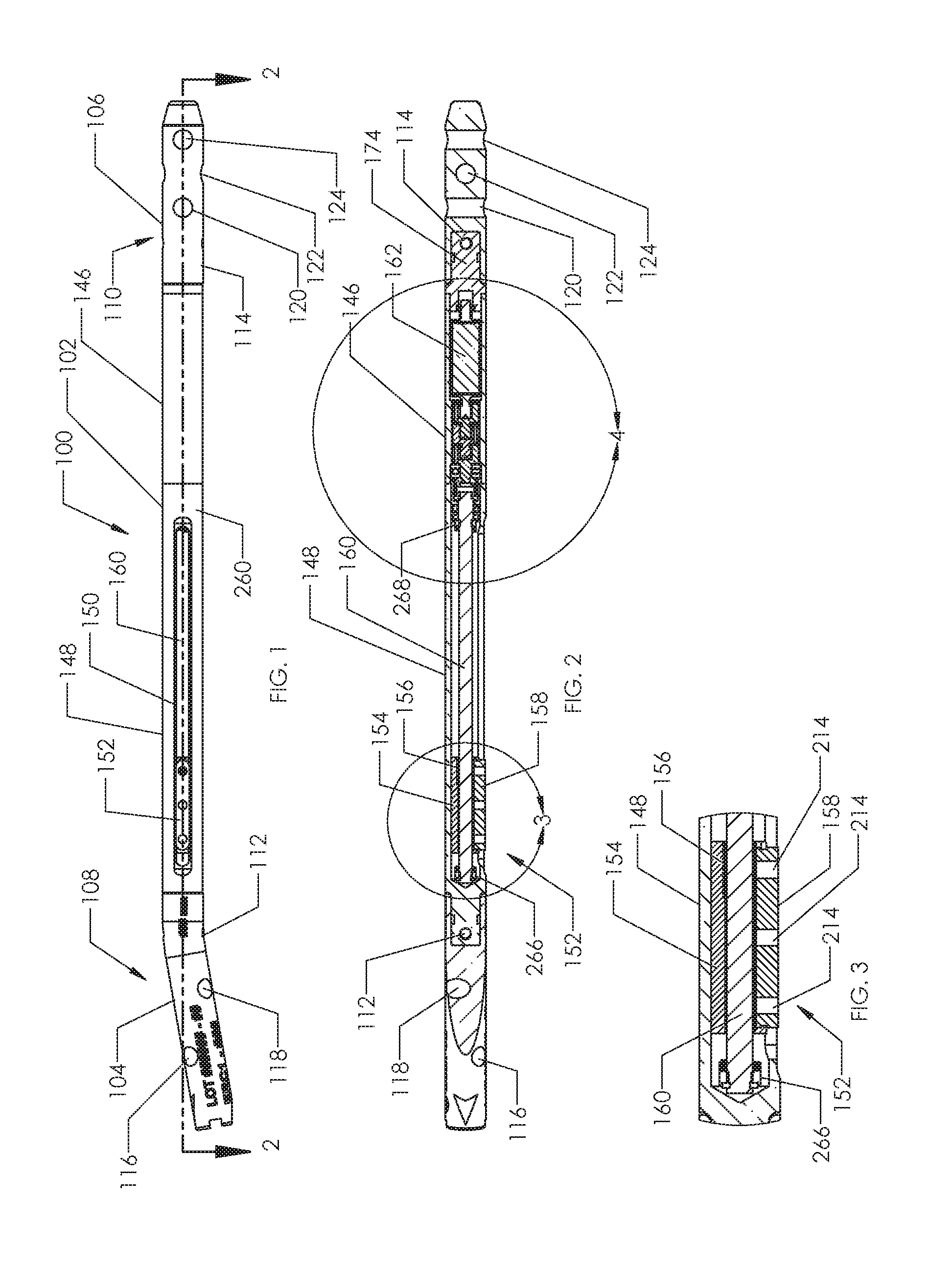
[0057]FIG. 1 illustrates an intramedullary bone transport device 100 in a “nail” configuration, having an actuator 102, a first extension rod 104 coupled to the actuator 102 at a first end 108 of the intramedullary bone transport device 100, and a second extension rod 106 coupled to the actuator 102 a second end 110 of the intramedullary bone transport device 100. First extension rod 104 and second extension rod 106 are secured to actuator 102 by set screws 112, 114. A variety of different extension rods are available, each having a particular angulation and length. In FIG. 1, first extension rod 104 is angled for use in the proximal tibia while second extension rod 106 is straight for use in the distal tibia. Multiple configurations are contemplated for tibial use, as well as antegrade use in the femur and retrograde use in the femur. Holes 116, 118, 120, 122, 124 are configured with specific diameters and orientations, in order to accommodate bone screws 126, 128, 130, 132, 134 fo...


PUM


Abstract

A bone transport system includes a nail having a proximal end and a distal end, the proximal end configured for securing to a first portion of bone, the distal end configured for securing to a second portion of bone. The system includes a housing having a wall with a longitudinal opening extending a length along a portion thereof. The system further includes a transport sled having a length that is shorter than the length of the longitudinal opening, the transport sled configured for securing to a third portion of bone, the transport sled further configured to be moveable along the longitudinal opening. The system further includes a magnetic assembly disposed within the nail and configured to be non-invasively actuated by a moving magnetic field, wherein actuation of the magnetic assembly moves the transport sled along the longitudinal opening. The system further includes a ribbon extending on opposing sides of the transport sled and substantially covering the longitudinal opening.

Description

INCORPORATION BY REFERENCE TO ANY PRIORITY APPLICATIONS[0001]This application is a continuation of U.S. patent application Ser. No. 14 / 451,190 (Dkt. No. ELPSE.025C1), filed Aug. 4, 2014, which is a continuation of U.S. patent application Ser. No. 13 / 655,246 (Dkt. No. ELPSE.025A), filed Oct. 18, 2012, now U.S. Pat. No. 9,044,281. Any and all applications for which a foreign or domestic priority claim is identified in the Application Data Sheet as filed with the present application are hereby incorporated by reference under 37 CFR 1.57.BACKGROUND OF THE INVENTIONField of the Invention[0002]The field of the invention generally relates to medical devices for treating disorders of the skeletal system.Description of the Related Art[0003]Distraction osteogenesis is a technique which has been used to grow new bone in patients with a variety of defects. For example, limb lengthening is a technique in which the length of a bone (for example a femur or tibia) may be increased. By creating a co...

Claims


Application Information

Patent Timeline
Patent Type & Authority Applications(United States)
IPC IPC(8): A61B17/72A61B17/84A61B17/88A61B17/86
CPCA61B17/7216A61B17/8872A61B17/846A61B17/86A61B17/84
Inventor POOL, SCOTTWALKER, BLAIR
Owner NUVASIVE SPECIALIZED ORTHOPEDICS INC
Why Eureka
Try Eureka