Cutting machine for cutting a glass sheet

a cutting machine and glass technology, applied in the direction of glass making apparatus, glass severing apparatus, manufacturing tools, etc., can solve the problems of increased production cost, complex structure, and heavy weight, and achieve the effect of convenient setting and control

Inactive Publication Date: 2017-02-09
BOTTERO SPA
View PDF25 Cites 0 Cited by
  • Summary
  • Abstract
  • Description
  • Claims
  • Application Information

AI Technical Summary

Benefits of technology

[0010]The purpose of the present invention is to provide cutting machine that, unlike the solutions known in the prior art, allows a force to be exerted uniformly on the sheets to press them against the support surfaces, and that is easy to set and control to accommodate any changes in the dimensions and position of the sheet on the support surfaces.
[0011]A further purpose of the present invention is to provide a cutting machine that is simple and economical to manufacture and has a low weight and costs.

Problems solved by technology

Efforts to stiffen the clamping bridges have, on the one hand, failed to solve the problem and, on the other, have made the structure more complex and heavier, and increased production costs.

Method used


Image

  • Cutting machine for cutting a glass sheet
  • Cutting machine for cutting a glass sheet
  • Cutting machine for cutting a glass sheet

Examples


Embodiment Construction

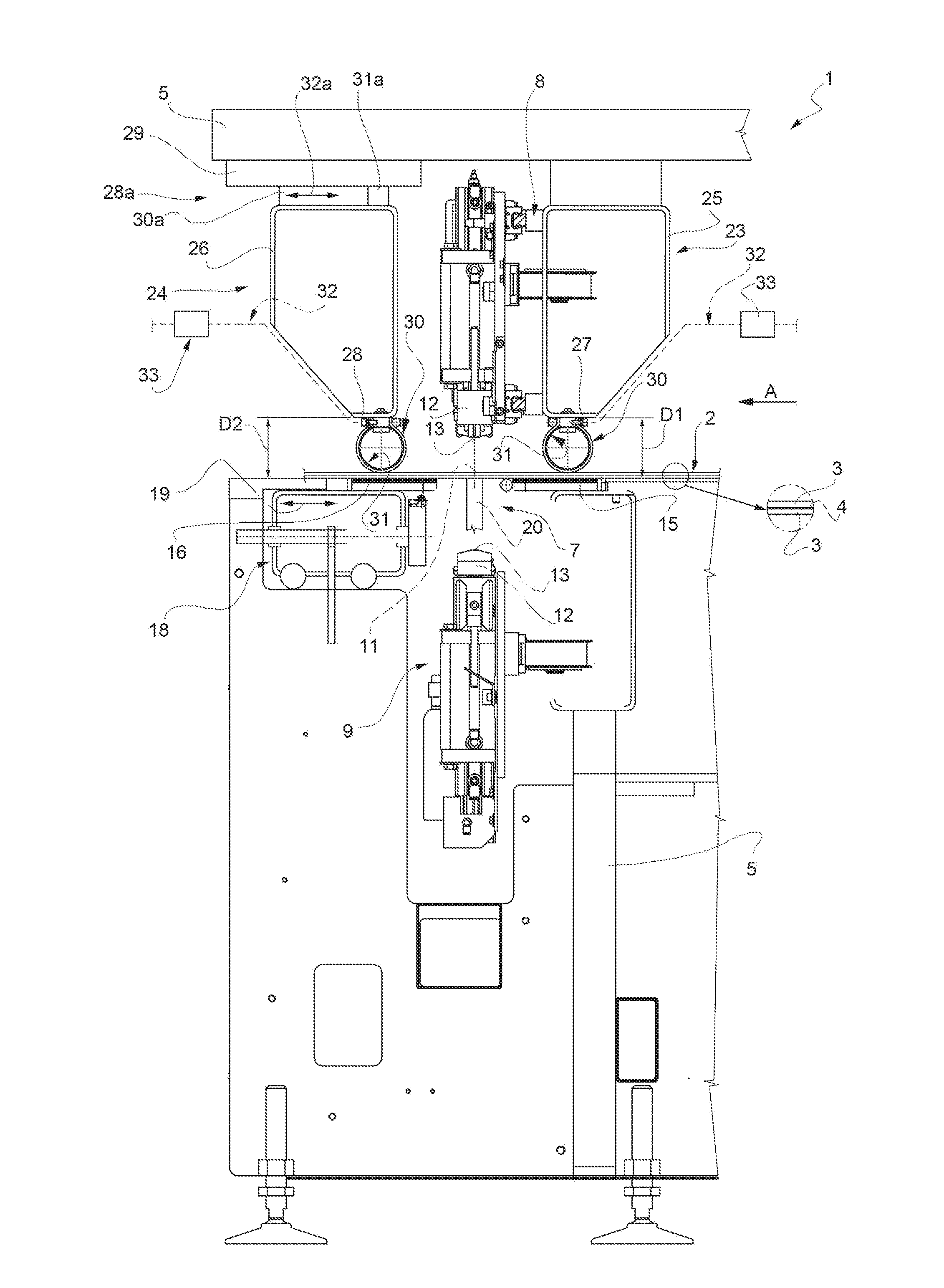
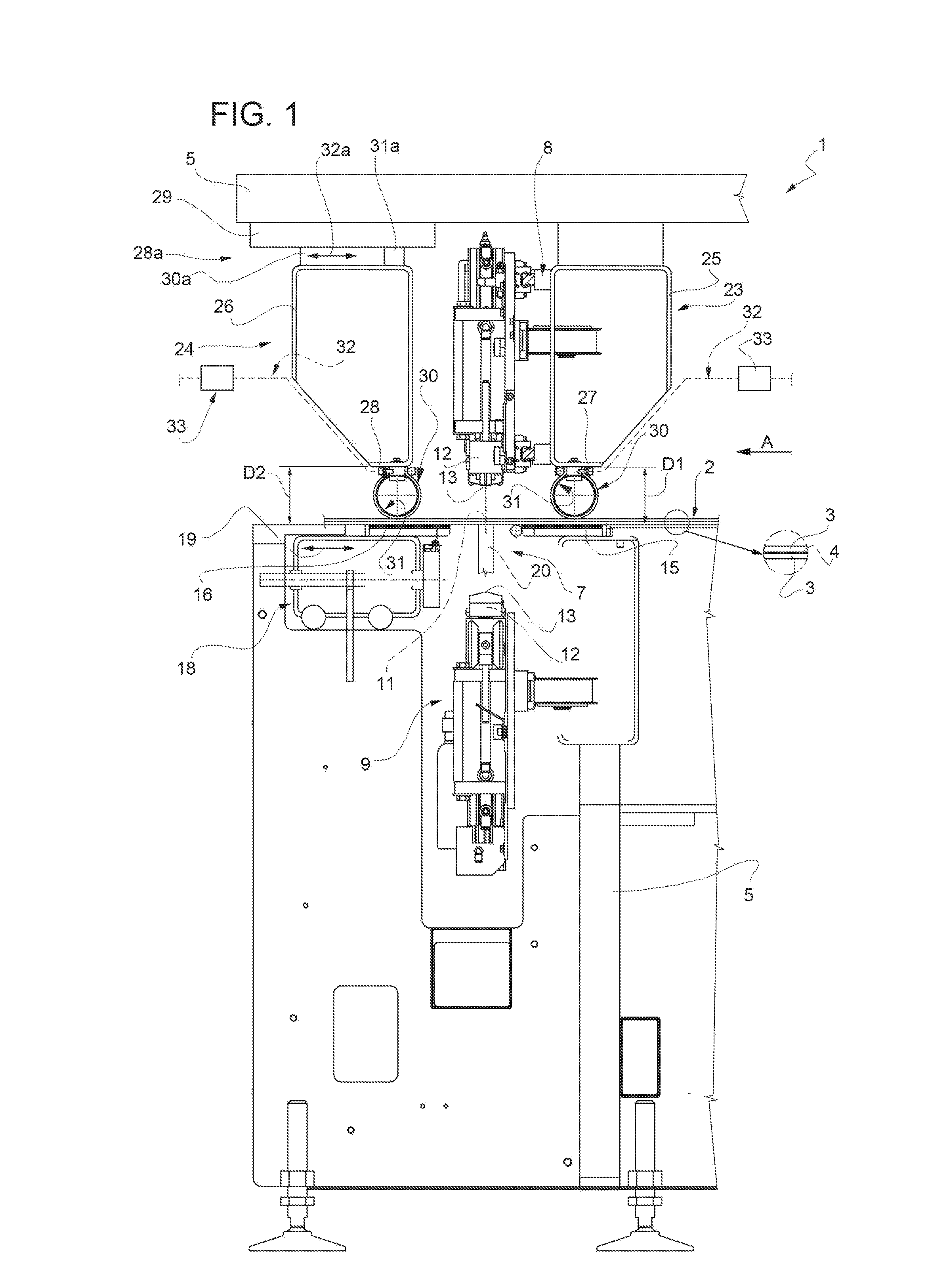
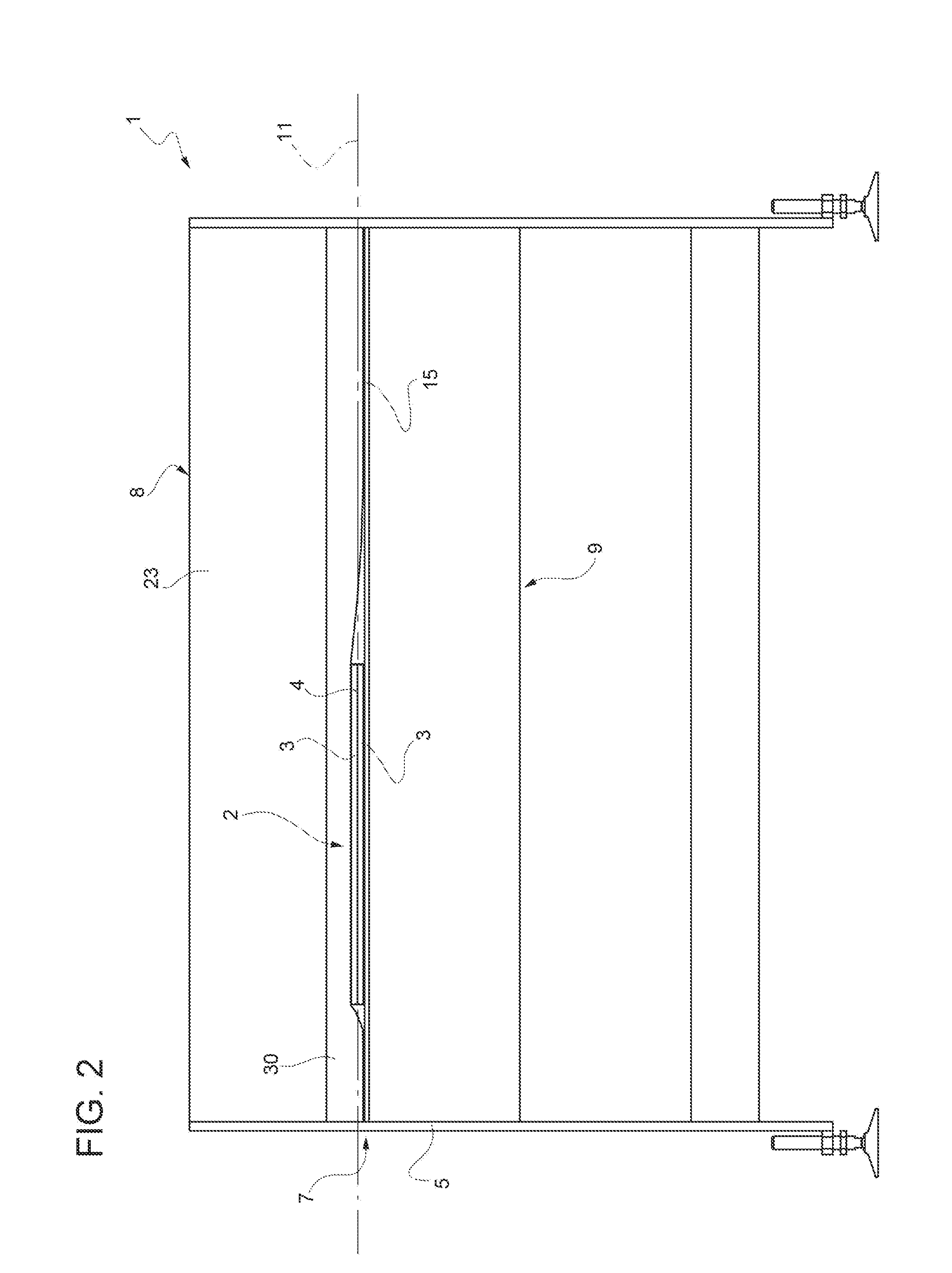
[0016]In FIGS. 1 and 2, denoted as a whole by reference numeral 1 is a cutting machine for cutting a laminated glass sheet comprising two lateral sheets 3 of glass and an intermediate layer 4 of thermoplastic material, generally known as PVB.

[0017]The machine 1 comprises a fixed frame 5, a sheet incision station 7, which is also fixed and houses a fixed upper incision bridge 8 and a fixed lower incision bridge 9, which are also of a type known in the prior art and therefore not described in detail here. On the lower incision bridge 9 and on the upper incision bridge 8, respective carriages 12 bearing respective incision wheels 13 of the glass sheets 3 are movable in opposite senses along a rectilinear direction of incision 11.

[0018]Again with reference to FIG. 1, the machine 1 further comprises two tables 15 and 16 to support the sheet 2 to be cut, coupled to the frame 5 in a known manner and arranged on opposite sides of the cutting station 7.

[0019]In the specific example of the ta...


PUM

PropertyMeasurementUnit
pressuresaaaaaaaaaa
pressuresaaaaaaaaaa
flexibleaaaaaaaaaa

Abstract

A sheet of glass is cut on a cutting machine having at least one support table of the sheet to be cut, an incision device for making at least one incision line on the sheet, and at least one thrust bridge for thrusting the sheet against the support table; the thrust bridge comprising a rigid cross member facing the support table and provided with at least one flexible hollow body integrally connected to the cross member in a position facing the support table; the hollow body delimiting at least one sealed chamber that can be pressurized by a pressurized fluid and extends for the whole length of the cross member.

Description

[0001]The present invention relates to a cutting machine for cutting a glass sheet, in particular a laminated glass sheet, to which the following description specifically refers but without any loss of generality.BACKGROUND OF THE INVENTION[0002]For cutting laminated glass sheets, i.e., those comprising two lateral sheets of glass and an intermediate layer of thermoplastic material, the use is known of cutting machines each comprising a fixed cutting station and two sheet supporting surfaces arranged on opposite longitudinal sides of the cutting station.[0003]The cutting station houses two fixed cutting bridges arranged facing one another and provided with respective motor-powered carriages movable in a fixed rectilinear cutting direction. Each carriage bears a respective incision wheel to make an incision line on the respective external glass sheet. The cutting station also houses a movable breaking member to break the glass sheet opposite the sheet that comes into contact with the...

Claims


Application Information

Patent Timeline
Patent Type & Authority Applications(United States)
IPC IPC(8): C03B33/03C03B33/023C03B33/07
CPCC03B33/03C03B33/023C03B33/078C03B33/033
Inventor GHINAMO, LEONARDOOLOCCO, GUIDO
Owner BOTTERO SPA
Why Eureka
Try Eureka