
Installation of Multi-Component Floor Mat

Pending Publication Date: 2017-02-09
MILLIKEN & CO
View PDF34 Cites 22 Cited by
  • Summary
  • Abstract
  • Description
  • Claims
  • Application Information

AI Technical Summary

Benefits of technology

The invention relates to a floor covering that can be easily installed and removed. The floor covering consists of a textile component and a base component that can be releasably attached to each other using magnetic particles and a magnetic coating. The textile component contains tufted pile carpet and a vulcanized rubber material containing magnetic particles. The base component can be a tray or a primary backing layer. The floor covering can also have additional components such as electronic sensors or a fastening system for securely attaching the textile component to the base component. The invention provides a simple and efficient method for installing and removing floor coverings that can be adapted to different floor surfaces.

Problems solved by technology

Because the coefficient of shrinkage is different for the textile component and the rubber component, the rubber edges of the base component can deform and cause wrinkling and buckling of the mat.
The rubber component can also experience premature rubber aging due to exposure to detergents and / or other chemicals during the laundering process.
Also, when the conventional one-part mat becomes dirty and needs laundering, the one-part mat is heavy and bulky making it difficult to transport.
The size and weight of the combined rubber base component and textile component takes up an inordinate amount of space in industrial, commercial, and / or residential washing and drying machines.
Furthermore, the entire one-part mat is exposed to heat and mechanical abrasion that may degrade the rubber comprising the mat.
These mechanisms function to prevent undesirable movement of the textile component on the base component because such movement could result in creating trip hazards.
However, because the attachment mechanisms can utilize a high amount of force to hold the top and bottom components of the floor mat together, the initial alignment and deployment of the top textile component onto the base component can present challenges.
Unless the initial alignment is perfect, the textile component will not be properly installed.
Due to the magnetic strength between the components, it is generally quite difficult to slide and move the textile component on the base component to correct any mis-alignment.
In this regard, even if the adherence force per unit area is low, the large surface area means that the total resistance to sliding and movement can be very high making realignment of the components very difficult.
If not corrected, mis-alignment of the textile component with the base component may create trip hazards within the floor mat and may be aesthetically not pleasing.

Method used


Image

  • Installation of Multi-Component Floor Mat
  • Installation of Multi-Component Floor Mat
  • Installation of Multi-Component Floor Mat

Examples


Embodiment Construction

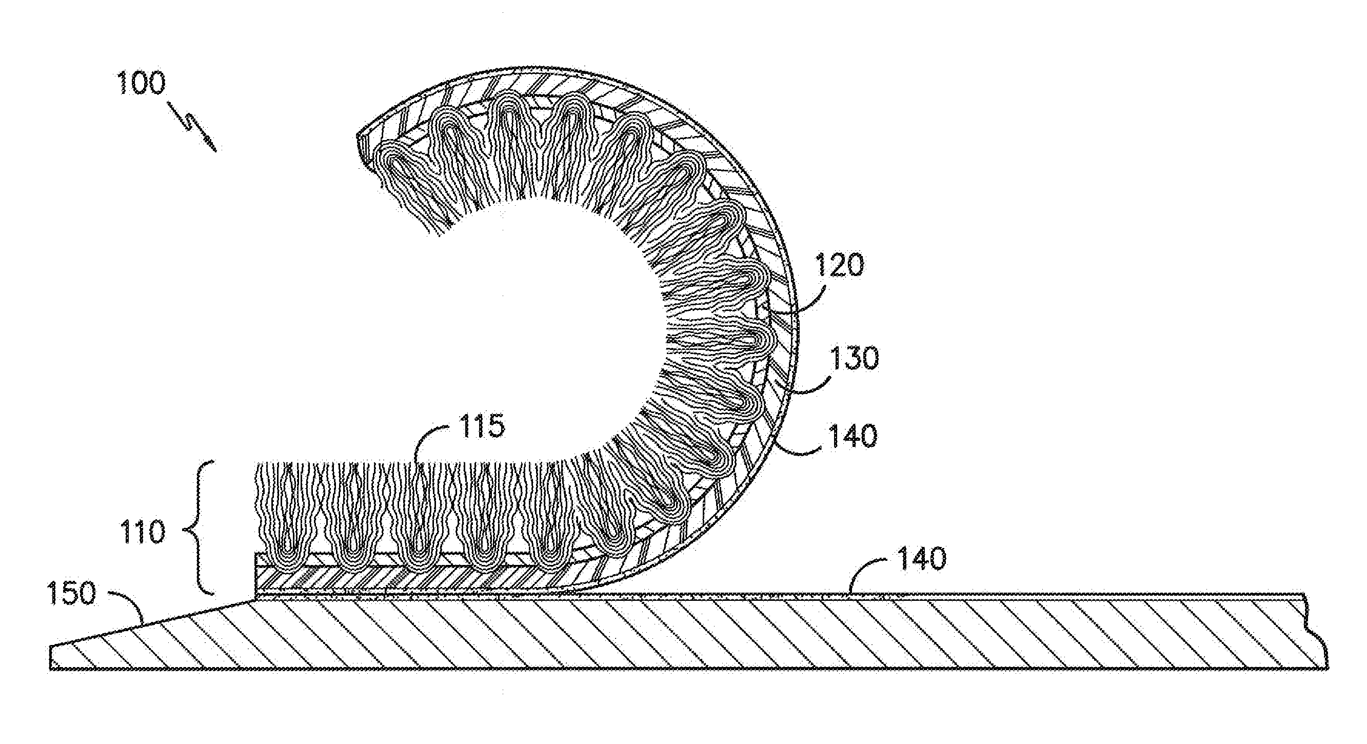
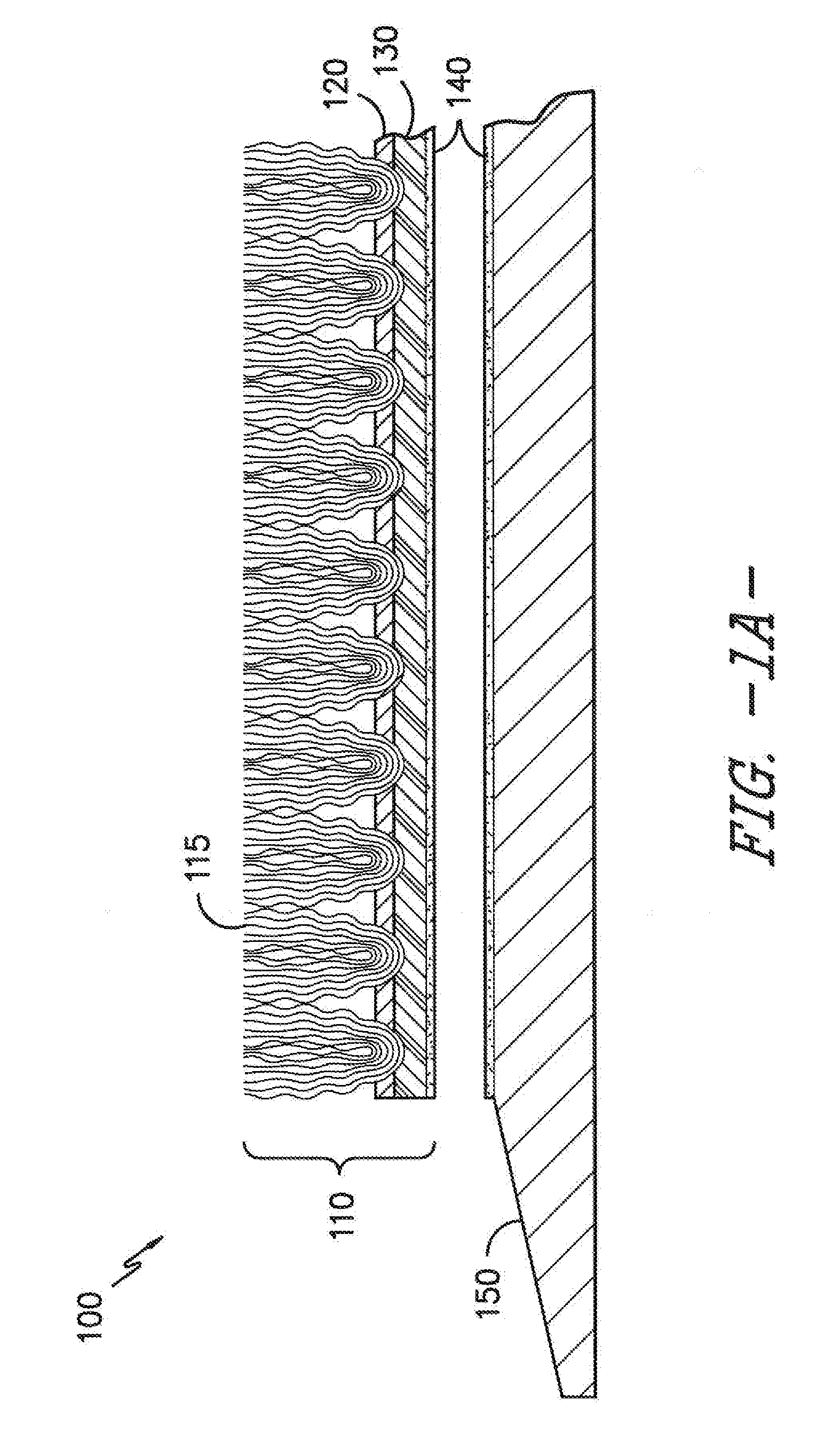
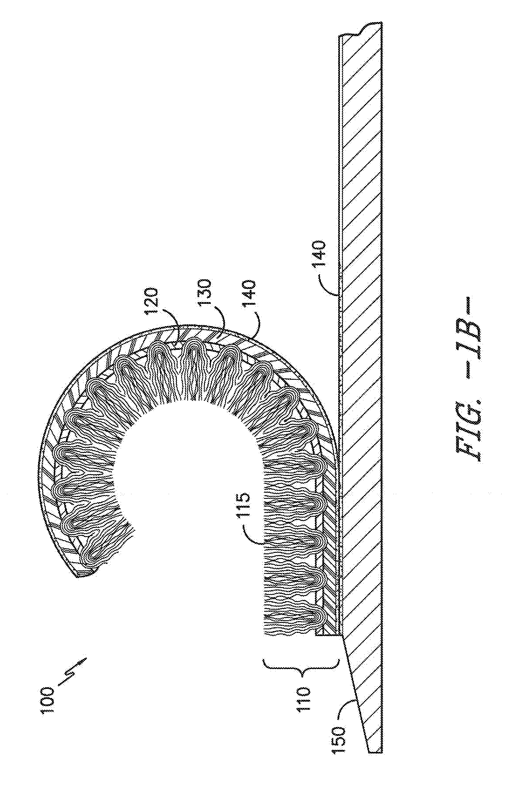
[0041]The present invention described herein is a method for installing multi-component floor mats. The method utilizes a variety of alignment and deployment mechanisms for properly and efficiently positioning the floor mats. The floor mats are comprised of a textile component and a base component.

[0042]The textile component and the base component are releasably attachable to one another via variety of attachment mechanisms. These include magnetic attraction (such as magnetic coatings, magnetic particles dispersed within a rubber or binder material, spot magnets, and the like), mechanical fasteners (such as Velcro® fastening systems, mushroom-shaped protrusions, grommets, and the like), adhesive attraction (such as cohesive materials, silicone materials, and the like), and combinations thereof. Each of these attachment mechanisms will be described in greater detail below.

[0043]Referring now to the Figures, FIG. 1A illustrates a floor mat 100 comprised of a textile component 110 and ...


PUM

PropertyMeasurementUnit
Fractionaaaaaaaaaa
Fractionaaaaaaaaaa
Fractionaaaaaaaaaa

Abstract

This invention relates to installation methods for a multi-component floor mat. The floor mat typically contains a textile component and a base component. Alignment and deployment of the textile component with the base component in an efficient manner is described herein.

Description

CROSS REFERENCE TO RELATED APPLICATIONS[0001]This application claims priority to U.S. Provisional Patent Application No. 62 / 201,149, entitled “Installation of Multi-Component Floor Mat” which was filed on Aug. 5, 2015, and which is entirely incorporated by reference herein.TECHNICAL FIELD[0002]This invention relates to installation methods for a multi-component floor mat. The floor mat typically contains a textile component and a base component. Alignment and deployment of the textile component with the base component in an efficient manner is described herein.BACKGROUND[0003]Conventional walk-off mats are made by bonding a tufted textile component to a base component typically made from a flexible rubber material. The flexible rubber material includes typical rubber materials as well as materials such as TPO, TPV, and elastomers that are generally not classified as rubbers, but can provide similar performance as rubbers. The rubber base component usually protrudes beyond the edges ...

Claims


Application Information

Patent Timeline
IPC IPC(8): D06N7/00
CPCD06N7/0071D06N2213/068D06N2209/045A47L23/266B32B2307/208Y10T428/23979B32B7/06B32B7/025A47G27/0206A47G27/0406D06N2211/066A47G27/02
Inventor LOVE, FRANKLIN S.SRIVASTAVA, SUDHANSHURAGHAVENDRAN, VENKATKRISHNAROBERTS, BRANDON T.PUTHILLATH, PADMAKUMARKITCHEN, DALE S.DAWSON, TY G.LI, XINDESOIZA, CHRISTOPHER A.
Owner MILLIKEN & CO
Features
  • Generate Ideas
  • Intellectual Property
  • Life Sciences
  • Materials
  • Tech Scout
  • Unparalleled Data Quality
  • Higher Quality Content
  • 60% Fewer Hallucinations
Learn More