Method for the integration of a nitrogen liquefier and liquefaction of natural gas for the production of liquefied natural gas and liquid nitrogen

a technology of nitrogen liquefier and natural gas, which is applied in the direction of liquefaction, solidification, cold treatment separation, etc., can solve the problems of underutilization of nitrogen producing equipment, inability to operate or not operate at optimal conditions, and waste of potential refrigeration capacity, so as to achieve more efficient and flexible methods of producing lng, the effect of reducing costs

Inactive Publication Date: 2017-02-09
LAIR LIQUIDE SA POUR LETUDE & LEXPLOITATION DES PROCEDES GEORGES CLAUDE
View PDF4 Cites 10 Cited by
  • Summary
  • Abstract
  • Description
  • Claims
  • Application Information

AI Technical Summary

Benefits of technology

[0009]The present invention is directed to a method and apparatus that satisfies at least one of these needs. In certain embodiments, the invention can provide a lower cost, more efficient and flexible method to produce LNG. For example, in certain embodiments, the invention can also include coproduction of liquid nitrogen (“LIN”). In additional embodiments, the invention may include varying the production rates of either or both the LIN and LNG, based on power costs, product demand, and / or supply levels.

Problems solved by technology

As such, in these locations, potential refrigeration capacity is wasted.
Additionally, there are instances in which producers of the nitrogen gas feeding the pipeline do not operate at 100% of equipment design capacity, and therefore, large nitrogen compressors are either not operating or not operating at optimum capacity.
As such, the nitrogen producing equipment may be designed to be underutilized during many operating scenarios when other systems are not able to accommodate increased loads.

Method used


Image

  • Method for the integration of a nitrogen liquefier and liquefaction of natural gas for the production of liquefied natural gas and liquid nitrogen
  • Method for the integration of a nitrogen liquefier and liquefaction of natural gas for the production of liquefied natural gas and liquid nitrogen
  • Method for the integration of a nitrogen liquefier and liquefaction of natural gas for the production of liquefied natural gas and liquid nitrogen

Examples


Embodiment Construction

[0102]While the invention will be described in connection with several embodiments, it will be understood that it is not intended to limit the invention to those embodiments. On the contrary, it is intended to cover all the alternatives, modifications and equivalence as may be included within the spirit and scope of the invention defined by the appended claims.

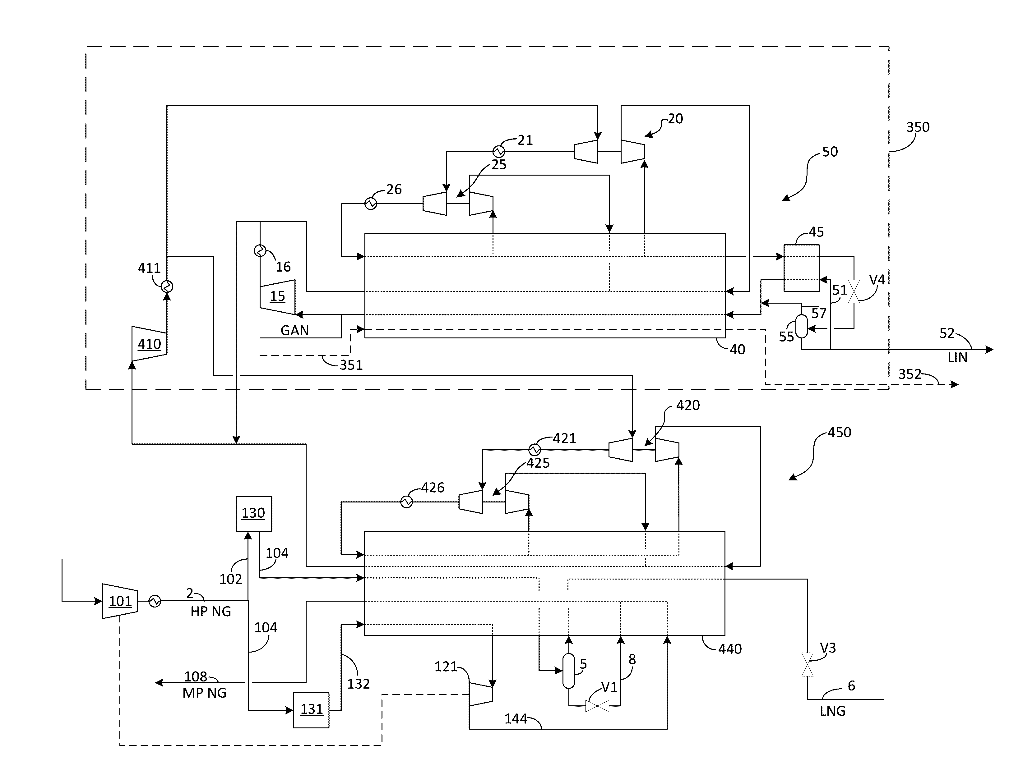
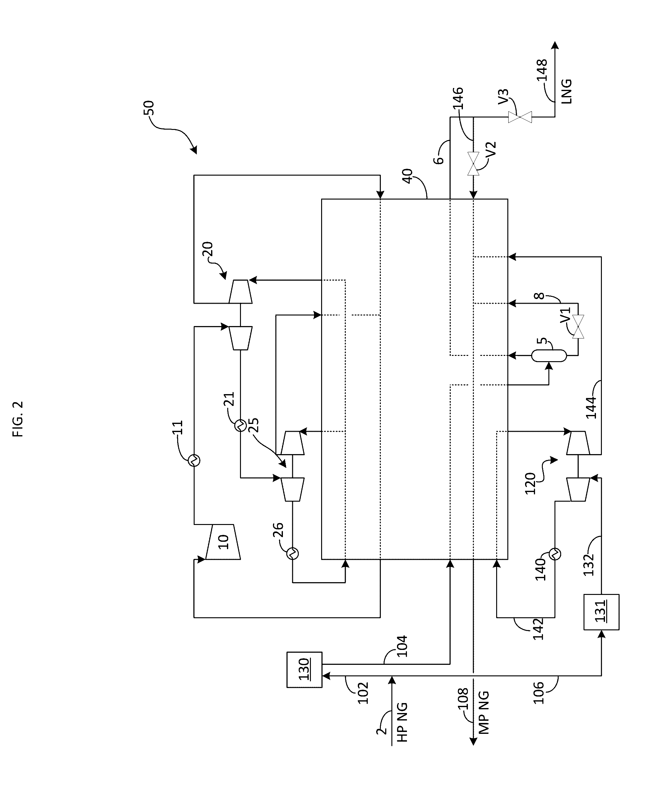
[0103]In one embodiment, the method can include integrating a natural gas letdown system with a nitrogen refrigeration cycle. In one embodiment, the nitrogen refrigeration cycle is a closed loop refrigeration cycle. In this embodiment, the natural gas letdown essentially provides “free” refrigeration energy since the natural gas would have been alternatively letdown across a valve (i.e., the resulting drop in temperature of the natural gas would have been absorbed by the surroundings and would not have been recovered in any meaningful way). With the addition of a natural gas turbine booster, LNG can be co-produced with a signi...


PUM


Abstract

A method for the integration of a nitrogen liquefier and liquefaction of natural gas for the production of liquefied natural gas and liquid nitrogen is provided. The method may include providing a nitrogen liquefaction unit and providing a natural gas liquefaction unit. Liquefaction of the nitrogen can be achieved via a nitrogen refrigeration cycle within the nitrogen liquefaction unit. Liquefaction of the natural gas can be achieved through the use of natural gas letdown and a second nitrogen refrigeration cycle. The two liquefaction units can be integrated via a common nitrogen recycle compressor, thereby providing significant capital savings.

Description

RELATED APPLICATIONS[0001]This application claims priority to U.S. Provisional Application Ser. No. 62 / 201,947, filed on Aug. 6, 2015, U.S. Provisional Patent Application No. 62 / 305,381, filed on Mar. 8, 2016, and U.S. Provisional Application Ser. No. 62 / 370,953 filed on Aug. 4, 2016, all of which are hereby incorporated by reference in their entireties.TECHNICAL FIELD OF THE INVENTION[0002]The present invention generally relates to a method for efficiently producing liquefied natural gas (LNG).BACKGROUND OF THE INVENTION[0003]Many locations utilize a high pressure (transmission) network and a lower pressure (distribution) network to supply natural gas through a local area. The transmission network typically acts as a freeway to economically send the gas over long distances to the general area, while the distribution network acts as the roads to send the gas to the individual users within a local area. Pressures of these networks vary by location, but typical values are between 30-8...

Claims


Application Information

Patent Timeline
Patent Type & Authority Applications(United States)
IPC IPC(8): F25J1/02F25J1/00
CPCF25J1/0208F25J2290/34F25J1/0015F25J1/0072F25J1/0292F25J2230/22F25J2270/08F25J2245/02F25J2240/44F25J2240/02F25J2210/06F25J2215/42F25J2230/60F25J2205/02F25J2220/60F25J2220/68F25J2220/66F25J2220/02F25J2210/60F25J2270/42F25J1/0022F25J1/0007F25J1/001F25J1/0037F25J1/004F25J1/0045F25J1/005F25J1/0052F25J1/0202F25J1/0204F25J1/0224F25J1/0232F25J1/0236F25J1/0264F25J1/0271F25J1/0274F25J1/0281F25J1/0288F25J2210/02F25J2215/62F25J2215/64F25J2220/64F25J2230/20F25J2230/30F25J2270/14F25J2270/16F25J1/0092F25J1/0238F25J1/0275F25J3/0257F25J3/04412F25J2205/04F25J2210/40F25J2220/44F25J2230/42F25J2240/12F25J2240/40F25J2245/42F25J2270/88F25J2290/12F25J2290/70
Inventor TURNEY, MICHAEL A.FARGES, ORIANEGUILLARD, ALAIN
Owner LAIR LIQUIDE SA POUR LETUDE & LEXPLOITATION DES PROCEDES GEORGES CLAUDE
Why Eureka
Try Eureka