

Image forming apparatus, method of controlling the same, and storage medium
- Summary
- Abstract
- Description
- Claims
- Application Information
AI Technical Summary
Benefits of technology
Problems solved by technology
Method used
Image

Examples
first embodiment
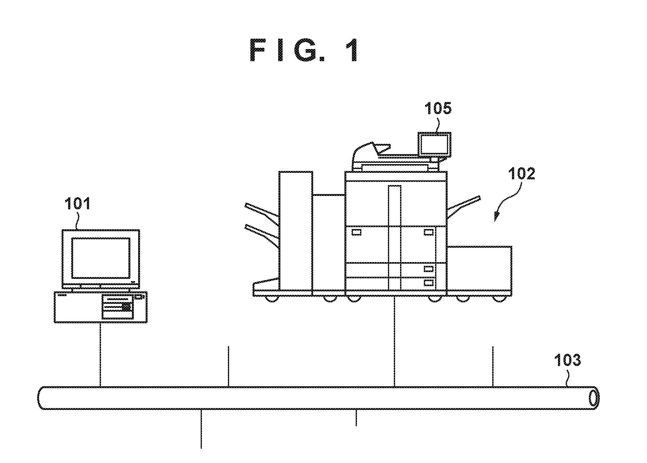
[0031]FIG. 1 is a view for illustrating a configuration of a print system in a first embodiment.
[0032]In this print system, a PC 101 and an image processing apparatus 102 are connected via a network 103. The image processing apparatus 102 is a multifunction processing apparatus (MFP) which prints an image on paper media (sheet) by a known electrophotographic technique. Note, this image processing apparatus 102 is not limited to an MFP, and an LBP (laser beam printer) or an ink-jet method printer may also be used.
[0033]The image processing apparatus 102 includes a display unit 105 capable of displaying information. The display unit 105 is a touch panel in which a user is prompted with operation instructions by displaying the information. The display unit 105 can accept various instructions from the user such as a print environment menu operation instruction, or a change of a print setting and a deletion of a print job.
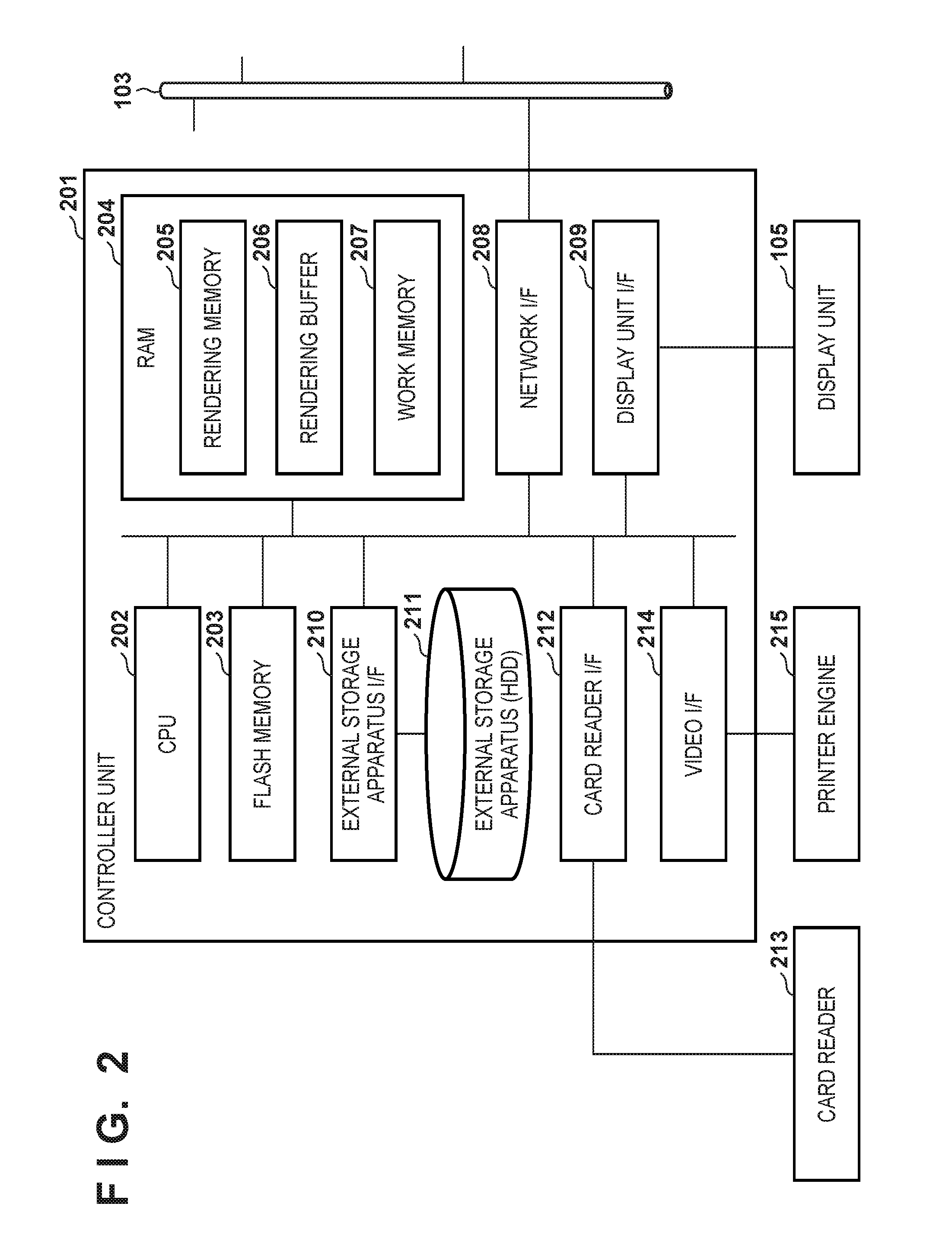
[0034]Also, a card reader 213 (FIG. 2) capable of reading informat...
second embodiment
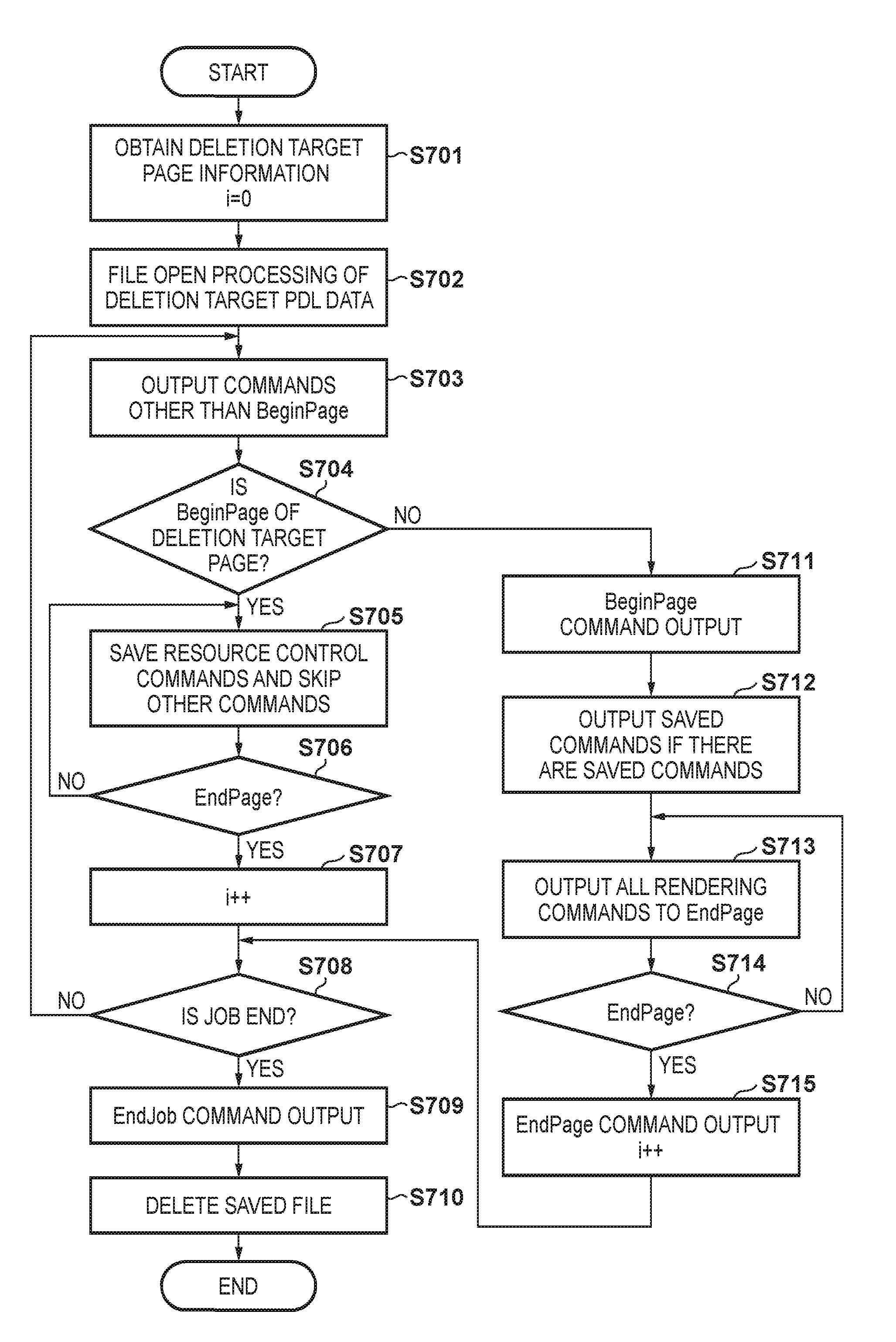
[0099]In the foregoing first embodiment, the resource control commands included in the deletion target page are saved (spooled) to a temporary file for work, and immediately after the start of processing for a subsequent page, those saved commands are inserted into that subsequent page. However, depending on the language specification of the PDL, page deletion can be performed without saving to the file for work. In other words, in the case where the parameters of the page start command are of a fixed length, or it is a PDL for which a maximum size can be specified, it is possible to output PDL data from which a particular page is deleted without spooling the resource control commands described in the deletion target page.
[0100]Accordingly, in the second embodiment, by first outputting the page start command (BeginPage) of the page targeted for deletion as a dummy, the resource control commands of the page targeted for deletion are output. After this, parameters of a page start comm...
third embodiment
[0116]The previously described print data processing unit 309 described in the first and second embodiments realizes processing for deletion of a particular page by deleting, or overwriting with a subsequent page, a page structure of a page targeted for deletion. However, the present invention is not limited to this, and it can be realized even by controlling so as not to output a blank sheet at a time of printing while leaving the page structure as is.
[0117]In conventional image processing apparatuses, as a function that the print data analyzing unit 304 includes, there is a function in which the page is interpreted as a blank sheet if not even a single command which contributes directly to the rendering processing is included in a page. Also, there are those that include a function for economizing blank sheets which controls the output of pages determined to be blank sheets in accordance with a user setting via the operation panel.
[0118]In the third embodiment, by using the functi...
PUM
 Abstract
Description
Claims
Application Information