Electronic device with capacitor bank linearization and a linearization method

Active Publication Date: 2017-02-09
NXP USA INC
View PDF1 Cites 10 Cited by
  • Summary
  • Abstract
  • Description
  • Claims
  • Application Information

AI Technical Summary

Problems solved by technology

As a consequence, since the oscillation frequency cannot be accurately controlled, even a larger number of s

Method used


Image

  • Electronic device with capacitor bank linearization and a linearization method
  • Electronic device with capacitor bank linearization and a linearization method
  • Electronic device with capacitor bank linearization and a linearization method

Examples


Embodiment Construction

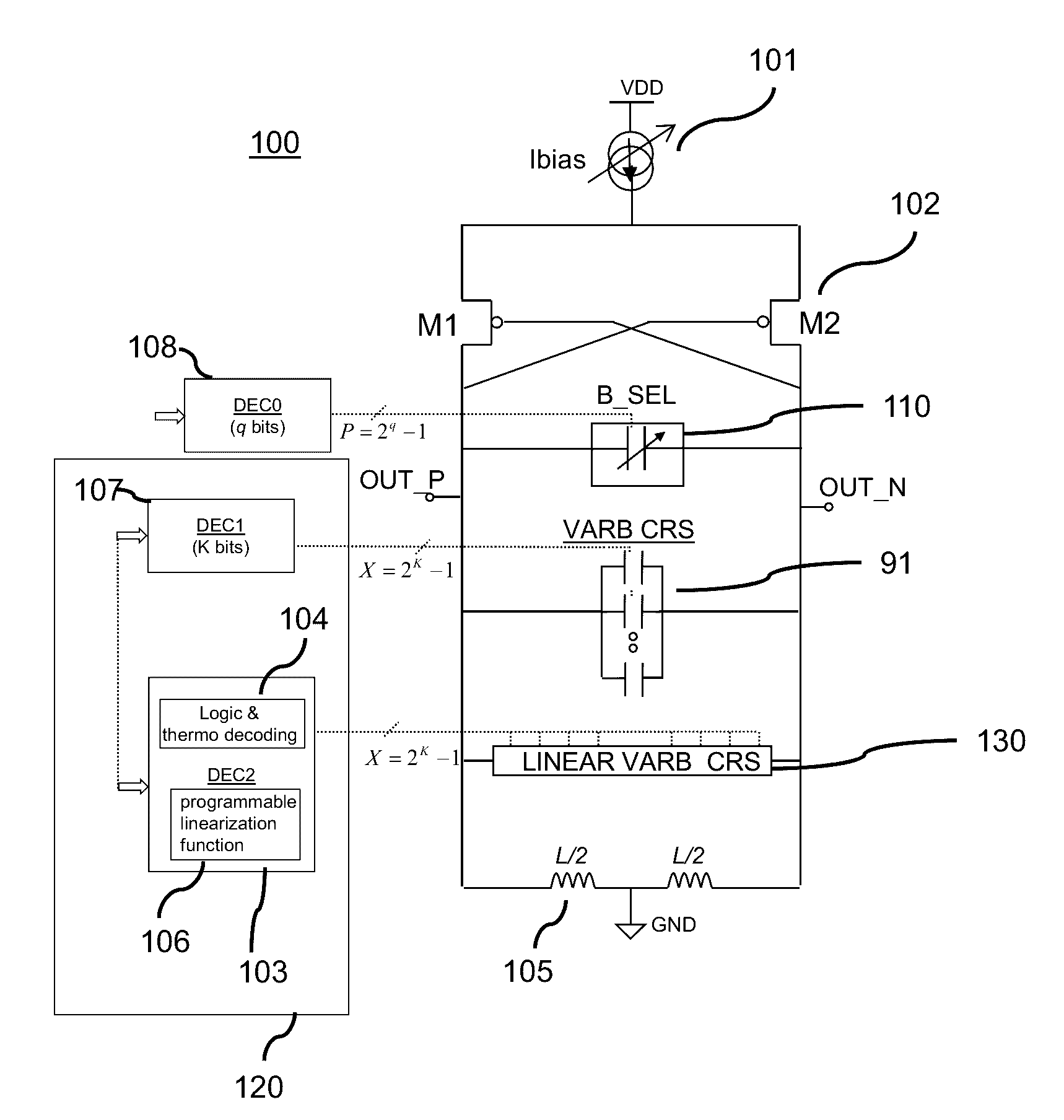
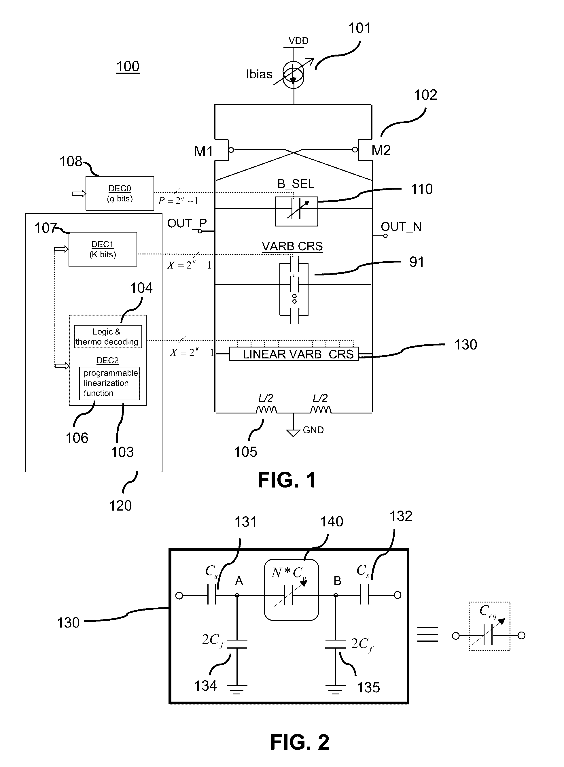
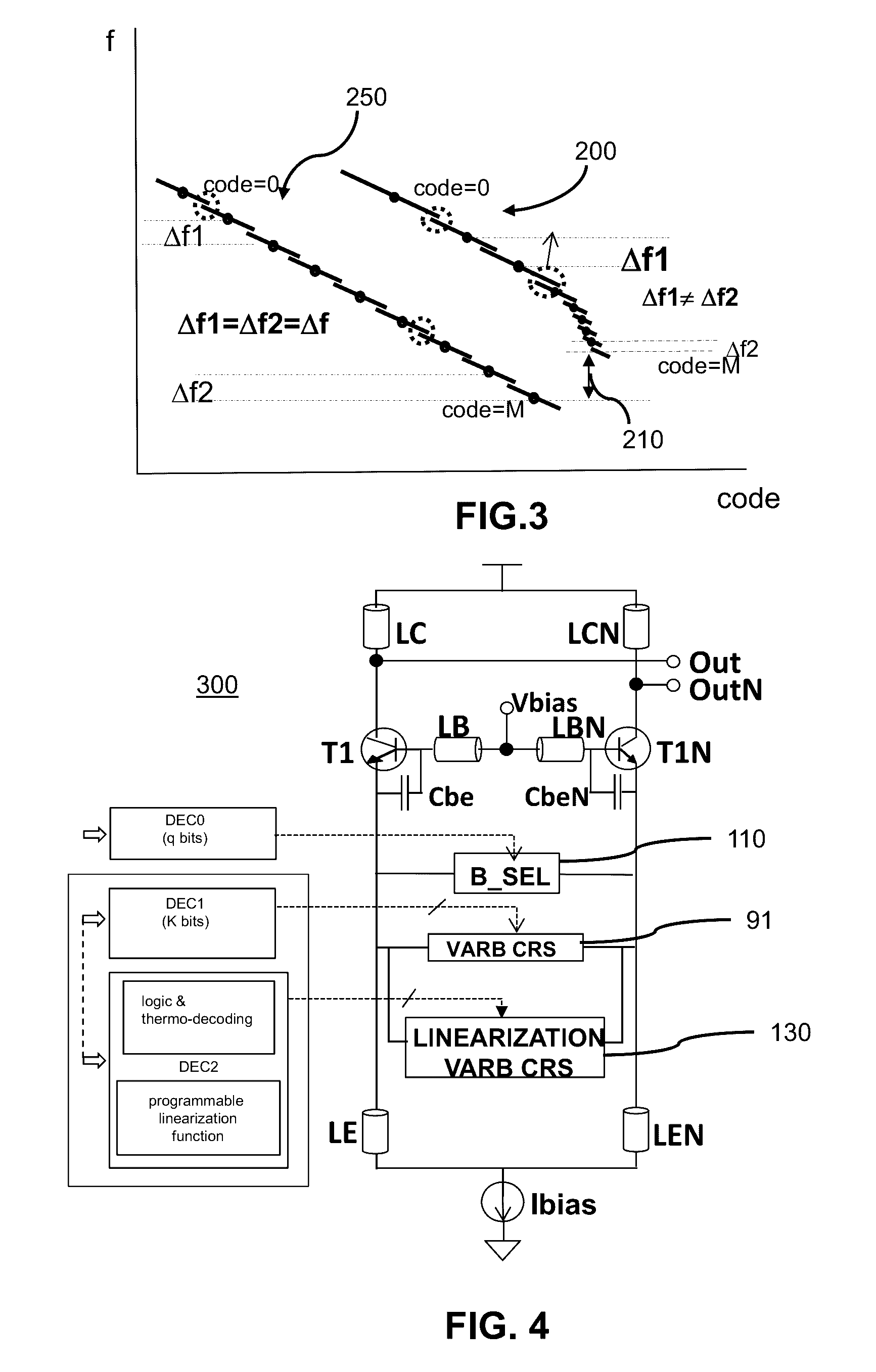
[0014]Embodiments of the present invention provide digital controlled oscillators that incorporate a capacitive arrangement of switchable capacitors whose equivalent total capacitance determines an output frequency of the respective oscillator (e.g., frequency of oscillation). The capacitive arrangement is suitably controlled for linearizing the total capacitance of the oscillators whose oscillation frequency is non linearly dependent of said total capacitance. The capacitive arrangement includes a controllable capacitor bank and a capacitive divider arranged in parallel with the capacitor bank. The capacitive arrangement is controlled to provide capacitance steps changing the oscillation frequency in a linearization frequency range of the oscillation frequency. The capacitive arrangement is controlled such that each capacitance step is variable over frequency in order to maintain said change of the oscillation frequency for each capacitance step, constant over frequency. The capaci...


PUM


Abstract

An electronic device comprises a controllable capacitor bank and a capacitive divider arranged in parallel with the capacitor bank and configured to linearize the capacitor bank in a linearization frequency range of a frequency characteristic of the electronic device. The capacitive divider comprises a series arrangement of a first series capacitance, and a main capacitor bank. A control circuit coupled to one or more control inputs of the capacitive divider and controllable capacitor bank is configured to modify the equivalent capacitance of the capacitive divider and the controllable capacitor bank for providing capacitance steps, each capacitance step being variable over frequency such that for each step a frequency change Δf of the frequency characteristic is maintained constant in the linearization frequency range.

Description

FIELD OF THE INVENTION[0001]This invention relates to an electronic device incorporating a capacitive divider for linearizing a controllable capacitor bank, an integrated circuit incorporating the electronic device and a method of linearizing a controllable capacitor bank of the electronic device.BACKGROUND OF THE INVENTION[0002]In ring oscillators or wide-band digital controlled oscillators, the oscillation frequency is typically controlled within a predetermined frequency range by a large number of switchable capacitors that change the total capacitance of the oscillation frequency in steps. Since the oscillation frequency is typically a non-linear function of the total capacitance, a fixed step change of the total capacitance results in a corresponding step change of the oscillation frequency which decreases with frequency if the step change of the total capacitance is positive, or increases with frequency if the step change of the total capacitance is negative.[0003]As a consequ...

Claims


Application Information

Patent Timeline
IPC IPC(8): H03B5/12
CPCH03B5/1265H03B5/1228H03B5/1212H03B5/1293H03B5/1215H03L7/099H01G15/00
Inventor PAVAO-MOREIRA, CRISTIANDOARE, OLIVIER VINCENTGOUMBALLA, BIRAMASALLE, DIDIER
Owner NXP USA INC
Why Eureka
Try Eureka