
Method for connecting an input/output interface of a tester equipped for control unit development

Active Publication Date: 2017-02-16
DSPACE DIGITAL SIGNAL PROCESSING & CONTROL ENG
View PDF3 Cites 8 Cited by
  • Summary
  • Abstract
  • Description
  • Claims
  • Application Information

AI Technical Summary

Benefits of technology

The invention aims to enhance the connection between the input / output interface of a tester and the model of a technical system in the tester.

Problems solved by technology

Consequently, configuration of the tester can take place more quickly, which significantly reduces the overall time for control unit development.

Method used


Image

  • Method for connecting an input/output interface of a tester equipped for control unit development
  • Method for connecting an input/output interface of a tester equipped for control unit development
  • Method for connecting an input/output interface of a tester equipped for control unit development

Examples


Embodiment Construction

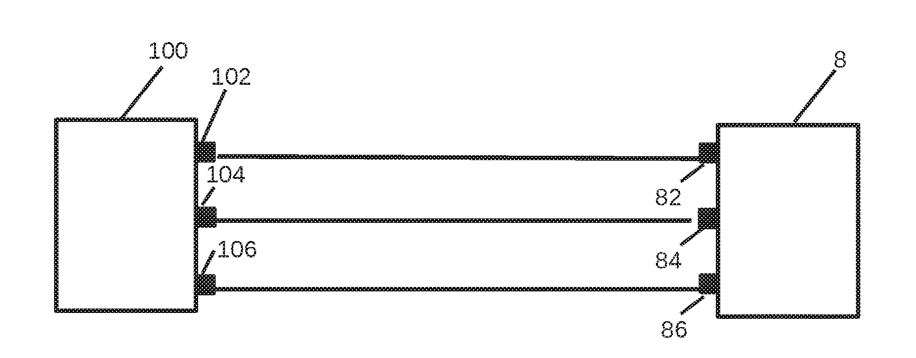
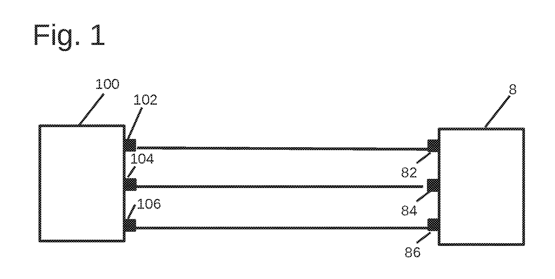
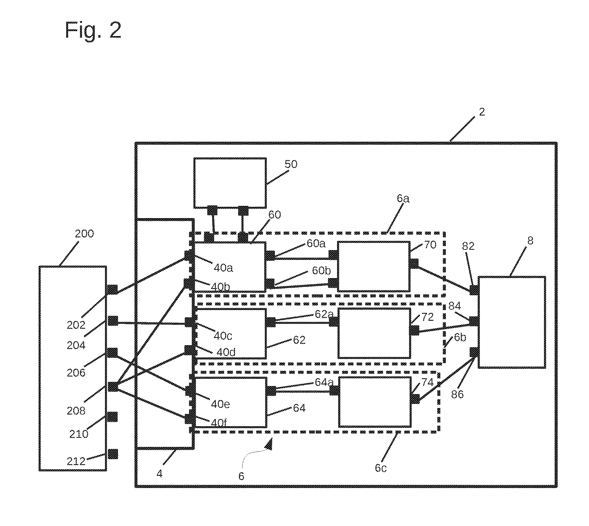
[0050]Described below by way of example with reference to FIGS. 1 and 2 is the way in which a tester that can test a hardware implementation of a control unit is configured according to one embodiment of the method according to the invention on the basis of a basic test model of the control unit. To this end, the block diagrams that are shown are described first, after which the exemplary embodiment of the method according to the invention is described.

[0051]FIG. 1 shows a basic test model 100 of a fan control. The fan control is an example of a control unit in the meaning of the present invention. The basic test model 100 is present in software and is intended and suitable for a purely computer-based basic test of the fan control. The basic test model 100 can also be referred to as a virtual control unit or as a virtual fan control.

[0052]The basic test model 100 has a first communication interface 102, a second communication interface 104, and a third communication interface 106. T...


PUM


Abstract

A method is provided for connecting an input / output interface of a tester equipped for control unit development to a model of a technical system present in the tester using an already-existing basic test model of a control unit. The input / output interface is designed for connecting a hardware implementation of the control unit or for connecting a technical system to be controlled, and the model to be connected to the input / output interface is a test model of the technical system to be controlled or a test model of the control unit. The already-existing basic test model of the control unit is accessed, and at least one communication requirement is extracted from the basic test model of the control unit.

Description

[0001]This nonprovisional application claims priority under 35 U.S.C. §119(a) to European Patent Application No. 15180733.6, which was filed in Europe on Aug. 12, 2015, and which is herein incorporated by reference.BACKGROUND OF THE INVENTION[0002]Field of the Invention[0003]The present invention relates to the development of control units, such as are used in the automotive industry or in the aviation industry, for example, for controlling technical systems such as, e.g., engines or brakes. In particular, the present invention relates to testers that are used in the development process for the control unit.[0004]Description of the Background Art[0005]The development of control units has become a highly complex process. New control units and new control functions should thus be tested as early in the development process as possible in order to verify general functionality and to set the direction for further development. Towards the end of the development process, it is important to...

Claims


Application Information

Patent Timeline
IPC IPC(8): G05B17/02G01R31/50
CPCG05B17/02G05B23/0213G05B19/0426G05B23/0254G05B2219/23276G05B2219/23446G05B2219/23456G05B19/0423G01R31/50G06F30/15
Inventor NAUNDORF, HOLGER
Owner DSPACE DIGITAL SIGNAL PROCESSING & CONTROL ENG
Learn More