Point-based risk score for managing environmental systems

a risk score and environmental system technology, applied in lighting and heating apparatus, heating types, instruments, etc., can solve the problems of over-representation of risk, increasing cooling equipment and energy costs, and rarely uniform level of redundancy in data centers. , to achieve the effect of high risk valu

Active Publication Date: 2017-02-16
VIGILENT CORP
View PDF10 Cites 12 Cited by
  • Summary
  • Abstract
  • Description
  • Claims
  • Application Information

AI Technical Summary

Benefits of technology

[0008]For example, historical and other data can be used to determine an influence model for each of one or more environmental maintenance modules, such as HVAC units, in an environmental maintenance system. An influence model can predict a change in a sensor value at a location for a corresponding change in an operation level of an actuator of one of the environmental maintenance modules. Based on the influence model and an operation level of the actuator, a reserve value can be determined for the location. A risk value for the location can be determined using a risk metric that may use the reserve value, a current sensor value at the location, and a threshold sensor value at the location.
[0009]Some embodiments can use a reserve metric and / or a risk metric to allocate environmental maintenance modules. For example, a new environmental maintenance module can be placed at a location with a low reserve value and / or a high risk value.
[0010]Some embodiments can use a reserve metric and / or a risk metric to allocate load. For example, in a data center, computational load can be allocated to a location with a high reserve value and / or a low risk value.

Problems solved by technology

However, the level of redundancy is rarely uniformly distributed across a data center.
In addition, some areas of a data center may have less effective cooling (e.g., because there are fewer or lower capacity HVAC units nearby).
If the reliability of a data center is treated atomically, this may lead to over-representing risk and increasing cooling equipment and energy costs, or under-representing risk and introducing the possibility of a catastrophic failure.

Method used


Image

  • Point-based risk score for managing environmental systems
  • Point-based risk score for managing environmental systems
  • Point-based risk score for managing environmental systems

Examples


example retail

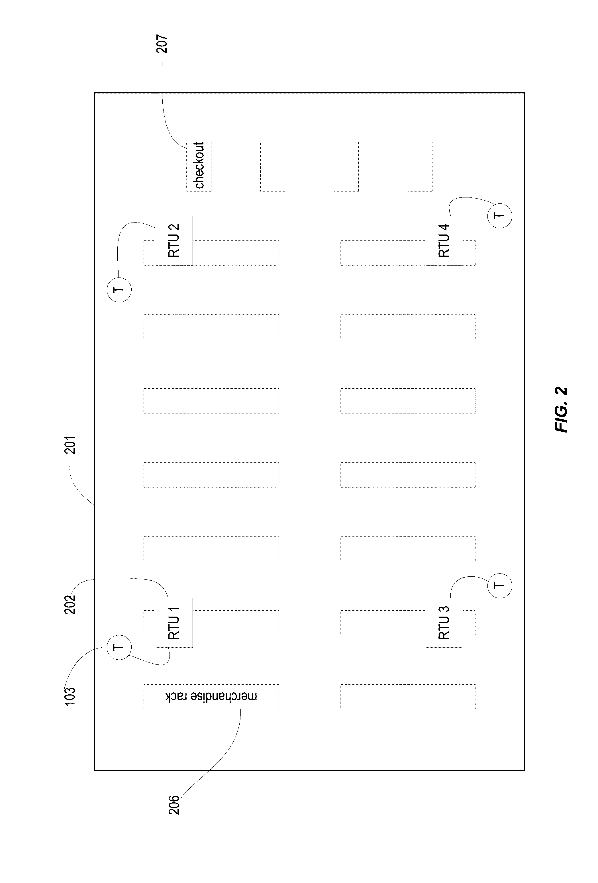
[0043]B. Example Retail Store

[0044]FIG. 2 shows a floor plan of a retail store comprising an environmental maintenance system according to an embodiment of the present invention. In this example, Perimeter wall 201 may be a perimeter wall of an environmentally-controlled space corresponding to the building of the retail store, or may be a space within the store. The environmental maintenance modules 202 shown in FIG. 2 are roof top units (RTU). As depicted, a wired communication can occur between the environmental maintenance modules 102 and sensors (T) 103 near that particular RTU, but wireless communications may also be used. The environmentally-controlled space can also include merchandise racks 206 and a store checkout counter 207.

[0045]C. Example Computer Room Air Handling Unit

[0046]FIG. 3 is a schematic diagram of a computer room air handling unit 300 according to an embodiment of the present invention. Computer room air handling unit 300 is an example of an environmental main...


PUM


Abstract

Methods are provided for calculating a reserve value or a risk value for various locations in an environmentally-controlled space such as a data center, and using the reserve value or risk value to allocate environmental maintenance modules and/or load. For example, an influence model can predict a change in a sensor value at a location for a corresponding change in an operation level of an actuator of one of the environmental maintenance modules. Based on the influence model and an operation level of the actuator, a reserve value can be determined for the location. A risk value for the location can be determined using a risk metric that may use the reserve value, a current sensor value at the location, and a threshold sensor value at the location.

Description

CROSS-REFERENCES TO RELATED APPLICATIONS[0001]The present application is a continuation of PCT application No. PCT / US2015 / 029266, filed May 5, 2015, which claims priority to U.S. Provisional Application No. 61 / 988,791, filed on May 5, 2014, the entire contents of which are herien incorporated by reference for all purposes.BACKGROUND[0002]Many modern datacenters use environmental maintenance systems including heating, ventilation, and air conditioning (HVAC) units to control indoor temperature, humidity, and other variables. It is common to have many HVAC units deployed throughout a data center. They are often floor-standing units, but may be wall-mounted, rack-mounted, or ceiling-mounted. The HVAC units often provide cooled air to a raised floor plenum, to a network of air ducts, or to the open air of the data center. The data center itself, or a large section of a large data center, typically has an open-plan construction (i.e., no permanent partitions separating air in one part of...

Claims


Application Information

Patent Timeline
Patent Type & Authority Applications(United States)
IPC IPC(8): G06Q10/06H05K7/20H05K7/14F24F11/00F24F11/76
CPCG06Q10/0635F24F11/006F24F11/0012F24F2011/0061H05K7/20836H05K7/1498F24F11/0015F24F11/30F24F2110/20F24F2110/10F24F11/62F24F11/77F24F11/32F24F11/58F24F11/63F24F11/52F24F2140/00G06F1/206G06F9/5094G06F1/20G06F1/3206
Inventor VARADI, PETER C.MAAS, WILLEMFEDERSPIEL, CLIFFORD C.
Owner VIGILENT CORP
Why Eureka
Try Eureka