Managing load sharing among multiple engines

Active Publication Date: 2017-02-23
CATERPILLAR INC
View PDF9 Cites 9 Cited by
  • Summary
  • Abstract
  • Description
  • Claims
  • Application Information

AI Technical Summary

Problems solved by technology

However, such a rigid load-sharing configuration may not be the most fuel efficient one.
Although Toruya offers a way of quantitatively determining a load-sharing configuration among multiple generator sets to

Method used


Image

  • Managing load sharing among multiple engines
  • Managing load sharing among multiple engines
  • Managing load sharing among multiple engines

Examples


Embodiment Construction

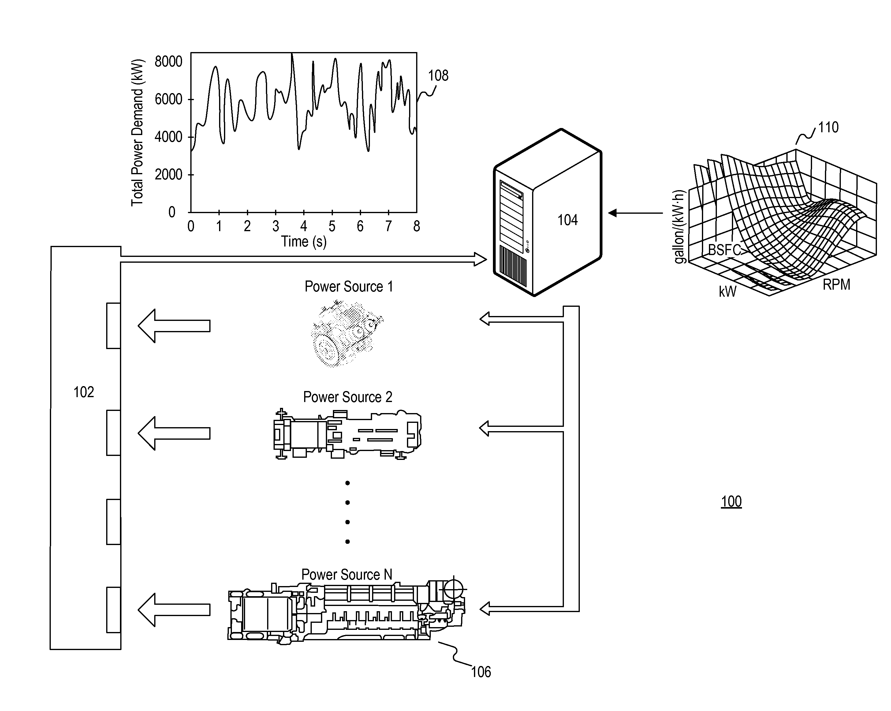
[0013]FIG. 1 illustrates an exemplary power system 100 used in a machine and configured to supply power to one or more loads. The machine includes multiple power generating units and may be a marine vessel, an airplane, a large vehicle, etc. For illustration purposes only, the following description assumes the machine to be a marine vessel. But those skilled in the art will appreciate the present disclosure is not limited to a marine vessel.

[0014]Referring to FIG. 1, the power system 100 may include, among other things, a load manager 102, a power distribution module 104, and a plurality of power sources 106. The load manager 102 determines a demand for power from the power sources 106 based on input received from a central controller of the vessel and / or on actual outputs (e.g., a performance) of the one or more loads. The power distribution module 104 determines a load share for each of the power sources 106 to reduce the total fuel consumption of the power sources 106. Each of th...


PUM


Abstract

A method and a system of managing load sharing among a plurality of power sources are disclosed. According to certain embodiments, the method includes determining a total power output to be directed from the plurality of power sources to at least one power consumer. The method also includes retrieving a Brake Specific Fuel Consumption (BSFC) curve associated with each of the plurality of power sources. The method further includes determining an operating priority for each of the plurality of power sources based on operating constraints associated with the respective power source. The method further includes determining a load share for each of the plurality of power sources based on at least the total power output, the BSFC curves, and the operating priorities.

Description

TECHNICAL FIELD[0001]The present disclosure relates generally to managing load sharing among multiple engines of a machine, and more particularly, to methods and systems of managing load sharing among multiple engines to reduce the total fuel consumption.BACKGROUND[0002]Mobile machines, such as marine vessels, often include multiple engines harnessed together to drive one or more primary loads (e.g., propellers) and various auxiliary loads (e.g., HVAC, lighting, pumps, etc.). These engines may have different operating ranges, speeds, etc. The engines can be mechanically connected to the loads or electrically connected to the loads by way of generators. In some applications, the loads of a vessel can be driven both mechanically and electrically in a hybrid arrangement.[0003]In typical marine applications, multiple engines are simultaneously operated to satisfy a power demand. Each of the multiple engines produces a share of the power demand proportional to the engine's capacity. For ...

Claims


Application Information

Patent Timeline
IPC IPC(8): F02D41/02G01L3/24F02D41/24
CPCF02D41/0205G01L3/24F02D41/2406F02D41/1406F02D25/00F02D29/06F02D2200/0625B63J3/04B63J2003/002
Inventor ZHANG, YANCHAICHANG, INSUCHASE, JAMESJANARDHAN, VIJAYCONVERSE, PERRY D.
Owner CATERPILLAR INC
Why Eureka
Try Eureka