
Storage battery charging and jointly outputting system of current-limiting power supply

一种输出系统、限电流的技术,应用在测量电流/电压、充电/放电电流/电压调节、电池电路装置等方向,能够解决成本及重量增加、影响电瓶寿命等问题

Active Publication Date: 2011-05-11
杨泰和
View PDF1 Cites 1 Cited by
  • Summary
  • Abstract
  • Description
  • Claims
  • Application Information

AI Technical Summary

Problems solved by technology

[0002] Due to its portability and practical capacity, the storage battery is often used as an emergency reserve power supply, electric vehicle and electric tool or as a DC power supply device. The battery will increase the cost and weight, or make the battery pack work at a deeper discharge depth and affect the life of the battery; the inventor's original authorized patent No. 02149231.X discloses an engine-driven battery auxiliary charging system that automatically monitors the operation , in order to use the engine generator as an auxiliary power source for driving load motors (or other loads) and to carry out timely auxiliary charging for stationary or vehicle-mounted storage batteries, so as to keep the storage batteries in a good state of storage. However, the inventor After research and testing, it is found that improvements can be made to further enhance its performance and make the system operation more perfect

Method used


Image

  • Storage battery charging and jointly outputting system of current-limiting power supply
  • Storage battery charging and jointly outputting system of current-limiting power supply
  • Storage battery charging and jointly outputting system of current-limiting power supply

Examples


Embodiment Construction

[0066] The present invention will be described in further detail below in conjunction with the accompanying drawings and embodiments of the present invention.

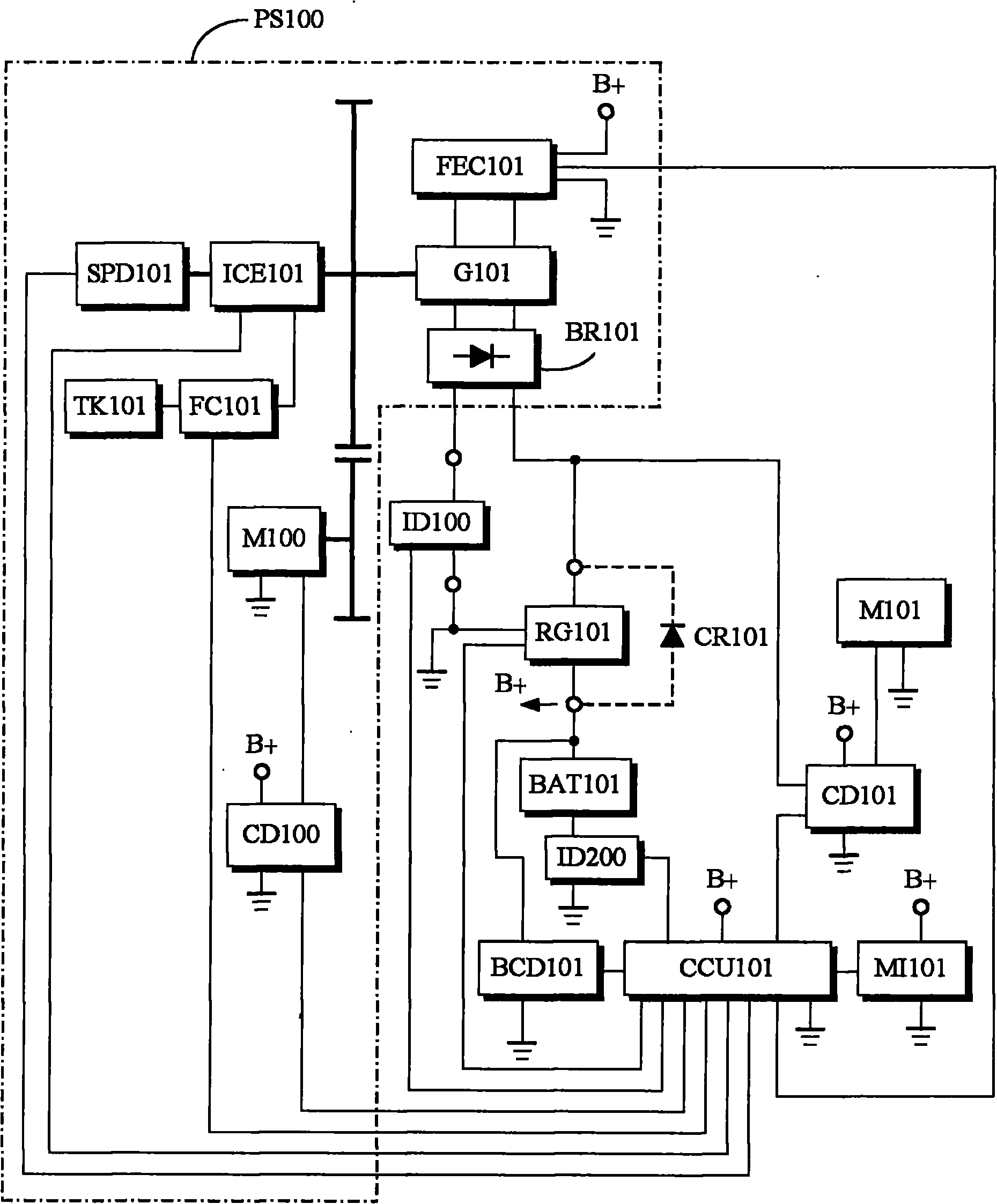
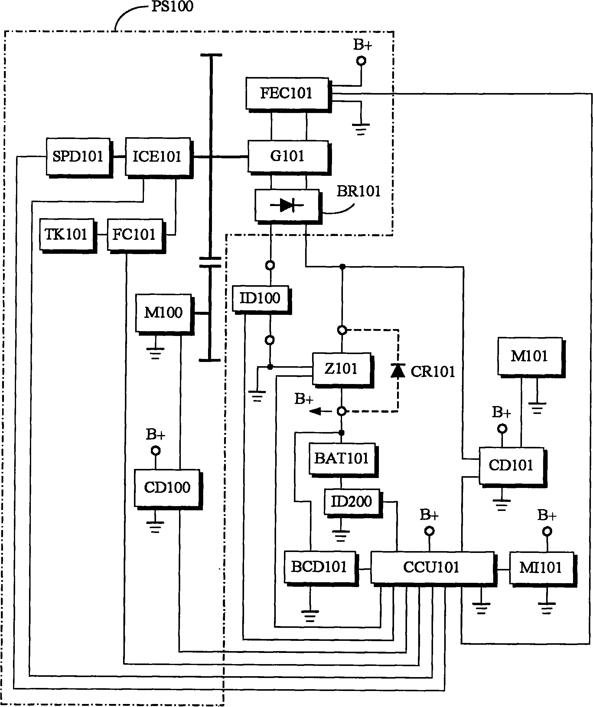
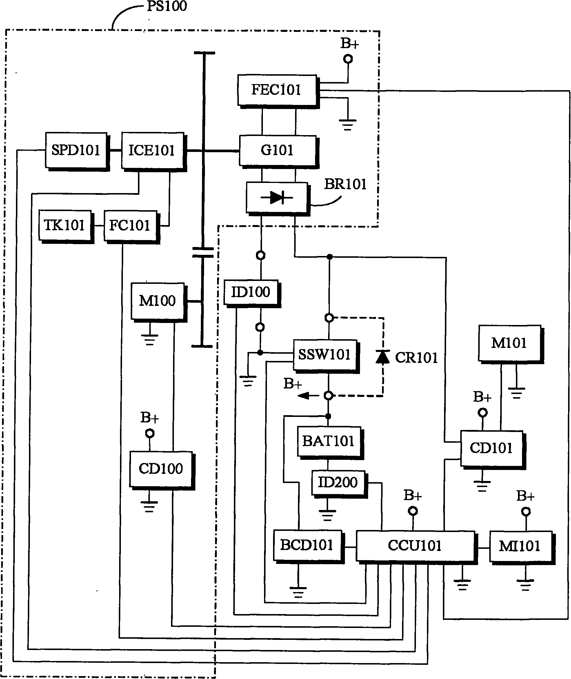
[0067] figure 1 Shown is the block diagram of the battery charging and cooperative output system of this current-limited power supply, and its main components are described as follows:

[0068] Battery BAT101: It is a secondary battery that can be used repeatedly for charge and discharge cycles, such as lead-acid, nickel-cadmium, nickel-metal hydride, nickel-zinc and other nickel-based batteries or lithium-based or zinc-based batteries or other secondary batteries. The battery can be fixedly installed in the circuit or be provided with a plug or socket group or connector for quick assembly or removal;

[0069] Battery storage state measurement device BCD101: for the terminal voltage of the storage battery BAT101 or the measured value of internal resistance or volume or specific gravity as a parameter, and including th...


PUM


Abstract

The invention relates to a storage battery charging and jointly outputting system of a current-limiting power supply. In the invention, an engine generator or a mains alternating current power supply is used, and the system specifically has the characteristic of limiting the maximum output current via an electromagnetic effect and / or has the characteristic of setting constant current lower than the maximum output current or setting an output close to the constant current so as to supply power to a load and charge a storage battery or supply power to the load together with the storage battery; and when an engine generator set is used as a power supply, during running, the engine runs with an optimal and / or better energy-saving revolution in an optimal and / or better torque region in the Brake Specific Fuel Consumption.

Description

technical field [0001] The invention relates to storage battery (storage battery or storage battery for short) technology, in particular to a storage battery charging and cooperative output system of a current-limited power supply. Background technique [0002] Due to its portability and practical capacity, storage batteries are often used as emergency power supplies, electric vehicles and electric tools, or as DC power supply devices. The battery will increase the cost and weight, or make the battery pack work at a deeper discharge depth and affect the life of the battery; the inventor's original authorized patent No. 02149231.X discloses an engine-driven battery auxiliary charging system that automatically monitors the operation , in order to use the engine generator as an auxiliary power source for driving load motors (or other loads) and to carry out timely auxiliary charging for stationary or vehicle-mounted storage batteries, so as to keep the storage batteries in a go...

Claims


Application Information

Patent Timeline
Patent Type & Authority Applications(China)
IPC IPC(8): H02J7/14H02J7/02H02J1/00G01R31/36G01R19/00
CPCH02J7/0068H02J7/007H02J7/04H02J7/1415H02J7/1438H02J7/34Y02T10/70
Inventor 杨泰和
Owner 杨泰和
Learn More