
Cage Valve with Instrumentation

a cage valve and instrumentation technology, applied in the direction of sliding valve, valve details, multiple way valves, etc., can solve the problems of slow erosion rate, damage to the well formation, and pressure on downstream equipmen

Active Publication Date: 2017-02-23
MASTER FLO VALVE
View PDF3 Cites 5 Cited by
  • Summary
  • Abstract
  • Description
  • Claims
  • Application Information

AI Technical Summary

Benefits of technology

The patent relates to a valve with a fluid flow path that can be restricted or closed. It includes a bonnet, stem, and a flow control member with a cage and flow control member. The valve also includes an end plate and a cavity with a transmitter to indicate erosion of the flow trim. The technical effects of the patent include providing a means to indicate the health of the flow trim and the ability to replace the valve components for sub-sea applications.

Problems solved by technology

Erosion of the flow trim may be extreme, causing catastrophic failure of the choke valve, which results in over pressurization of the downstream equipment or damage to the well formation due to excessive flow.
Production interruptions occur with surface and sub-sea facilities when there is erosion (i.e., wear) of the valve flow trim to the point that the flow trim needs to be replaced.
Most areas of the flow trim such as the ports, the plug or the flow collar are not accessible and / or hospitable locations for sensors or transmitters to be inserted.
As well, once erosion starts to occur, the rate of erosion may accelerate to the point that the flow trim, and thus the choke, can fail in a very short period of time.
In sub-sea wellheads, maintenance cannot be performed manually.

Method used


Image

  • Cage Valve with Instrumentation
  • Cage Valve with Instrumentation
  • Cage Valve with Instrumentation

Examples


Embodiment Construction

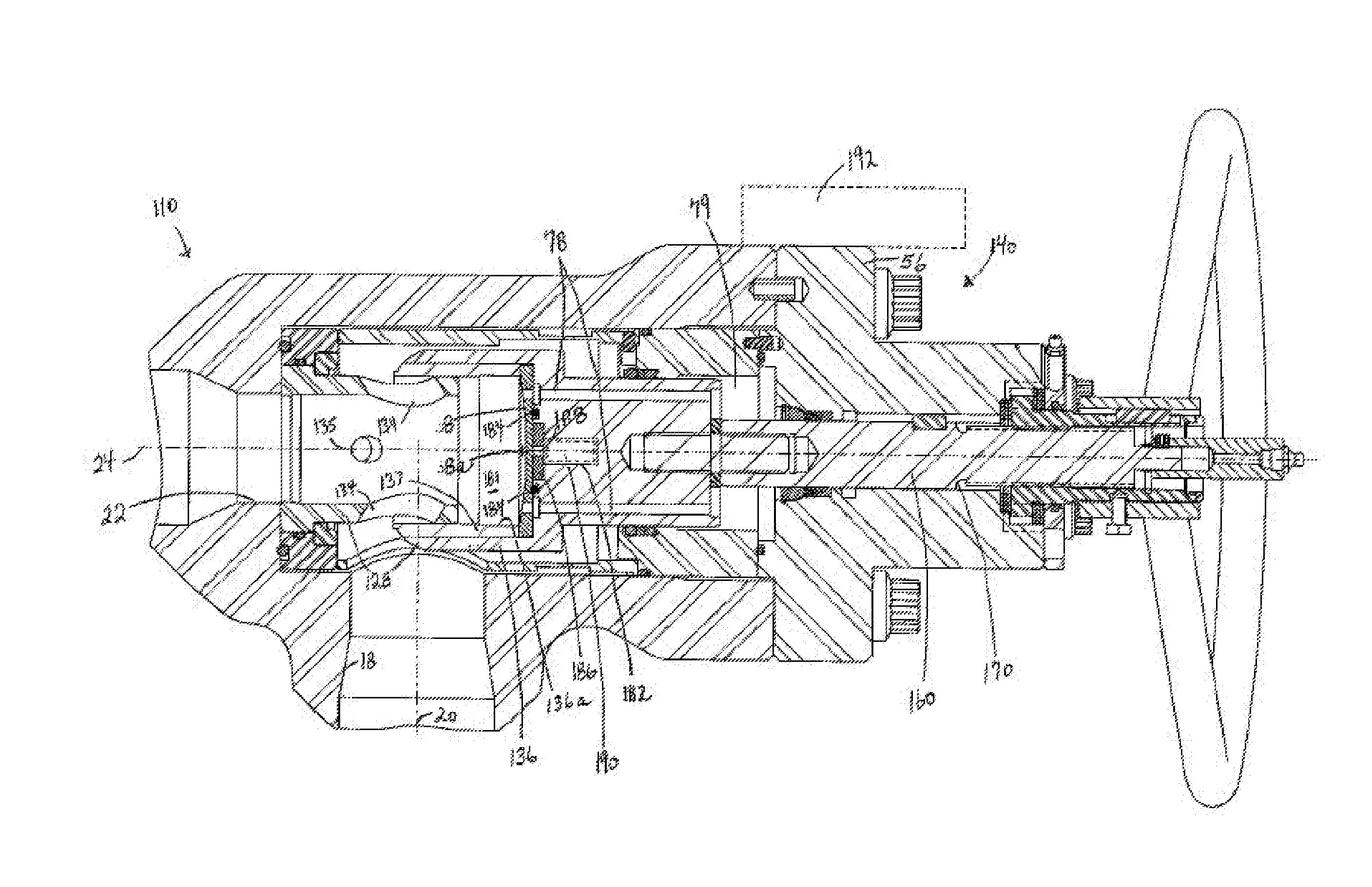
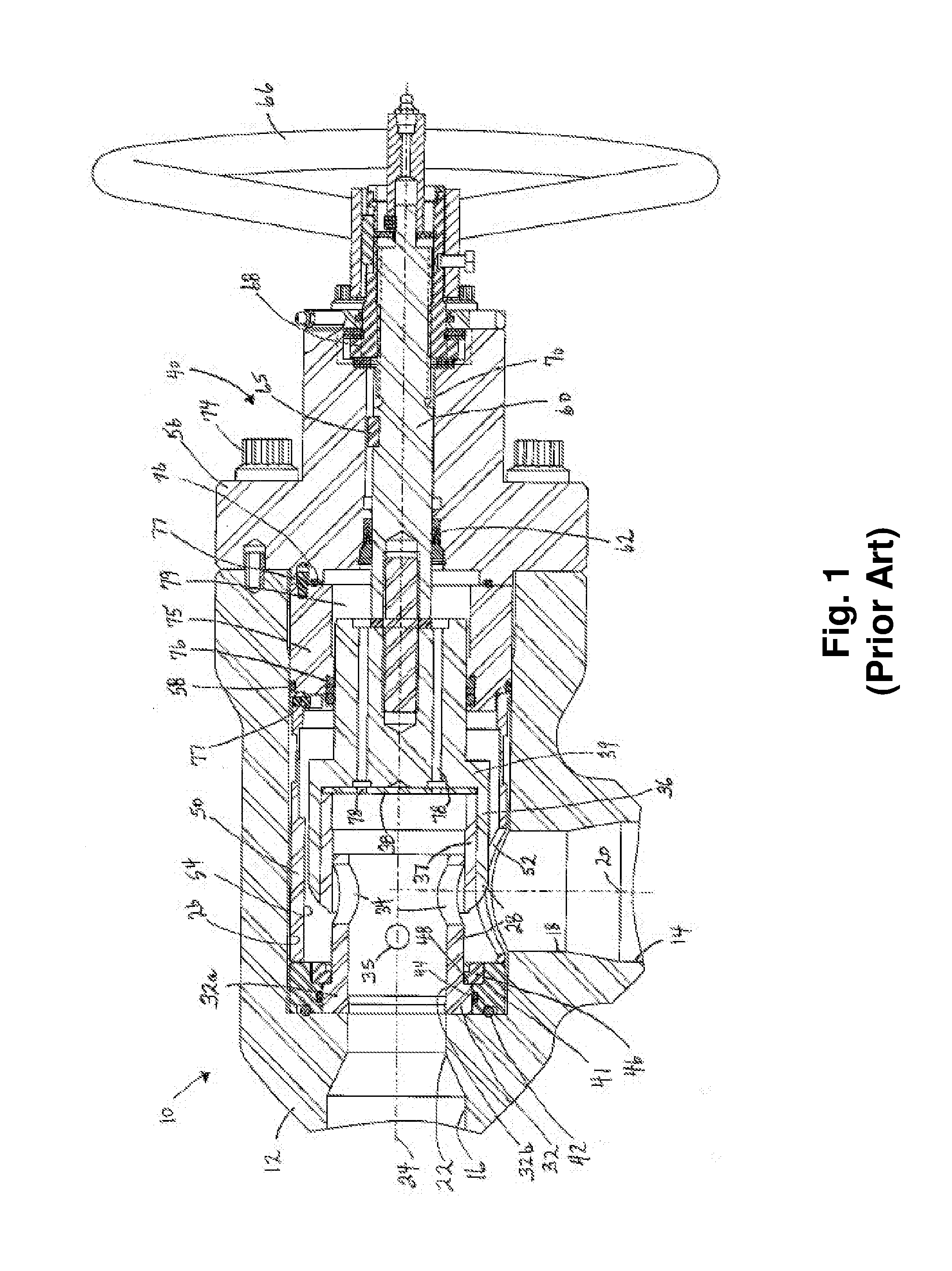
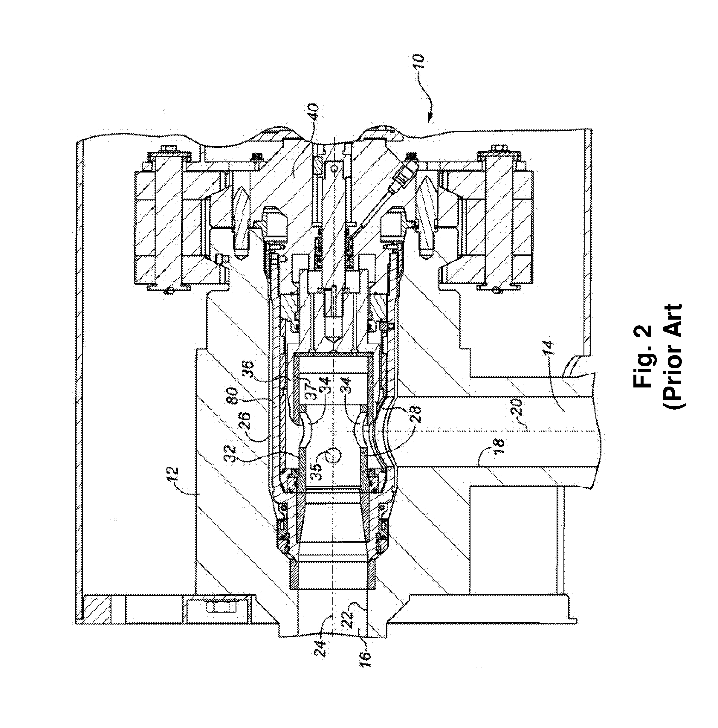
[0028]The flow trim and cage components described herein have wide application in cage valves in which the flow trim includes a stationary ported cage component and a flow control member which slides externally or internally along the side wall of the cage to cover and uncover the port(s) in the cage. The flow trim and cage components described herein have particular application in choke valves and control valves of the external sleeve (flow collar) and inner cage valve design. Two exemplary types of external sleeve / inner cage valves are shown and described in FIGS. 1-3 herein to illustrate the invention, but the invention has wider application. For example, the cage component may be adapted for use with other known external sleeve inner cage valves, for example cage valves in which the cage component is fitted at or into the outlet of the valve, for example by threading. The cage component may be adapted for use in external sleeve / inner cage valves in which the cage component is mu...


PUM


Abstract

A cage valve, flow trim components, and method for signalling erosion of flow trim. The valve is of the type having flow trim arranged across an inlet bore and aligned with an outlet bore, and including a stationary tubular cage and an internal or external flow control member such as a plug or flow collar slidable along the side wall of the cage to cover or uncover flow ports in the side wall. The flow control member includes an end plate which closes an upstream end of the cage. A cavity is formed in the flow control member upstream of the end plate. A transmitter, such as a proximity beacon, positioned in the cavity transmits a first signal indicative of intact flow trim when no fluid is in the beacon cavity and transmits a zero value signal or no signal indicative of eroded flow trim when fluid enters the cavity.

Description

CROSS-REFERENCE TO RELATED APPLICATIONS[0001]This application is a U.S. Nonprovisional application filed under 35 U.S.C. §111(a) which claims the benefit of U.S. Application No. 62 / 208,459, filed Aug. 21, 2015. This application is hereby incorporated by reference in its entirety.FIELD OF THE INVENTION[0002]This invention relates to a cage valve with instrumentation to signal erosion, a method of signalling erosion in a cage valve, and flow trim components of a cage valve to signal erosion.BACKGROUND[0003]A choke valve is a throttling device commonly used as part of an oil or gas field wellhead. It functions to reduce the pressure of the fluid flowing through the valve. Choke valves are placed on the production “tree” or “manifold” of an oil or gas wellhead assembly to control the flow of produced fluid from a reservoir into the production flow line, and is used on wellheads or manifolds located on land, offshore, or beneath the surface sub-sea of the ocean (sub-sea). Examples of cho...

Claims


Application Information

Patent Timeline
Patent Type & Authority Applications(United States)
IPC IPC(8): F16K47/08F16K27/04E21B34/02F16K25/00F16K37/00F16K11/07F16K25/04
CPCF16K47/08F16K11/0716F16K27/041E21B34/02F16K25/005F16K37/0041F16K37/005F16K25/04F16K3/26F16K3/267
Inventor BOHAYCHUK, LARRY J.FINLAYSON, DOUGLAS A.
Owner MASTER FLO VALVE
Learn More