Measurement apparatus, lithography apparatus, and method of manufacturing article

a measurement apparatus and lithography technology, applied in the direction of photomechanical apparatus, instruments, using reradiation, etc., can solve the problems of plurality of corner cubes, inability to unlimitedly decrease the change in the optical path of reflected light caused by the movement of objects, and difficulty in accurately measuring this measurement apparatus. to achieve the effect of accurate measurement of position

Inactive Publication Date: 2017-02-23
CANON KK
View PDF2 Cites 7 Cited by
  • Summary
  • Abstract
  • Description
  • Claims
  • Application Information

AI Technical Summary

Benefits of technology

[0006]The present invention provides a measurement apparatus advantageous in, for example, accurately measuring the position of an object.

Problems solved by technology

It may become difficult for this measurement apparatus to accurately measure the position of an object (reflecting surface) if the object moves and the position and angle of the optical path of light (reflected light) reflected by the reflecting surface change relative to the optical path of light (incident light) to be incident on the reflecting surface.
However, the miniaturization of the corner cubes has its limit, so it is impossible to unlimitedly decrease the change in optical path of reflected light caused by the movement of the object.
That is, using only the reflecting surface on which the plurality of corner cubes are arrayed may become insufficient to accurately measure the position of the object.

Method used


Image

  • Measurement apparatus, lithography apparatus, and method of manufacturing article
  • Measurement apparatus, lithography apparatus, and method of manufacturing article
  • Measurement apparatus, lithography apparatus, and method of manufacturing article

Examples


first embodiment

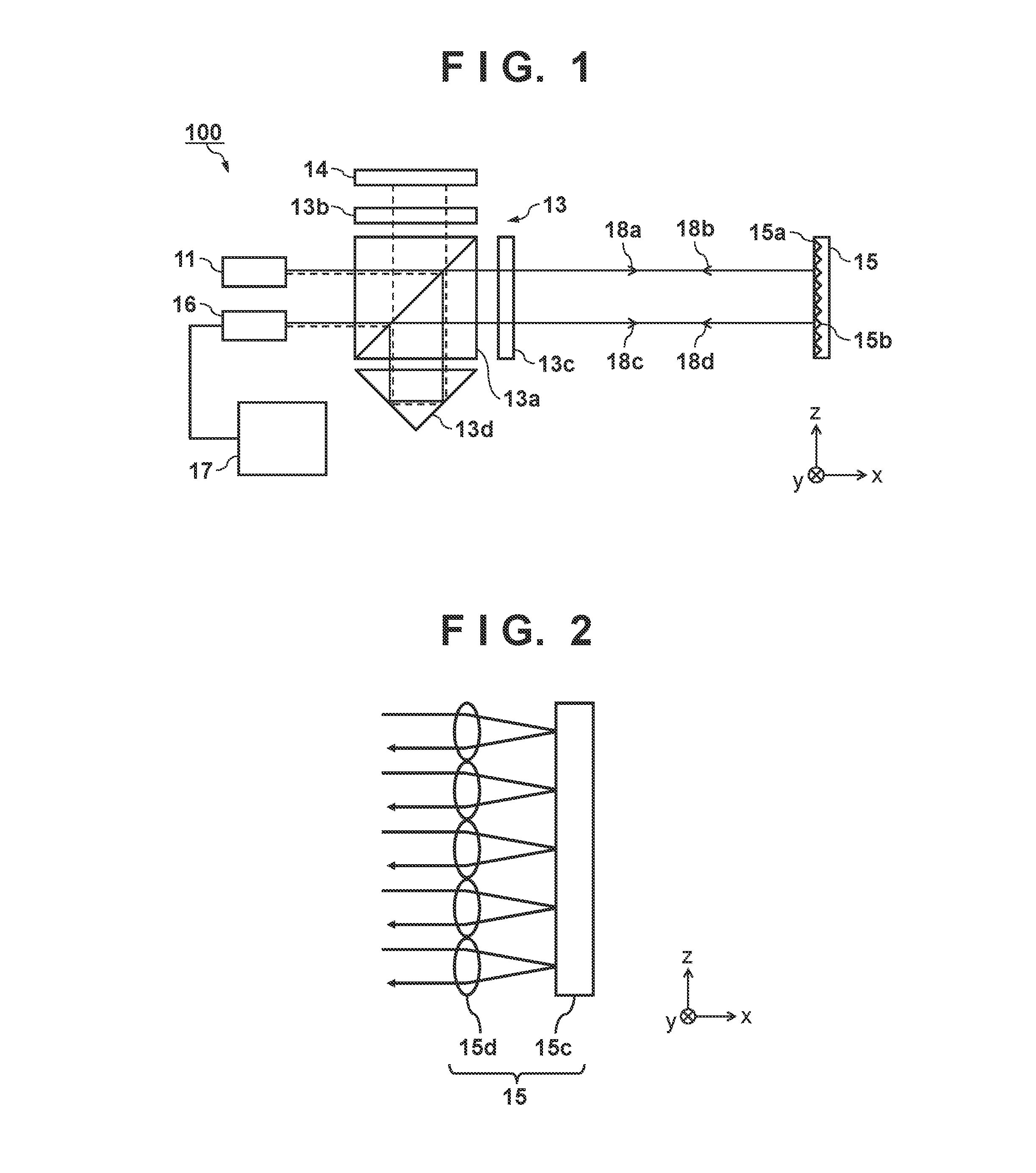
[0027]A measurement apparatus 100 of the first embodiment according to the present invention will be explained with reference to FIG. 1. The measurement apparatus 100 of the first embodiment includes, for example, a light source 11, an optical system 13, a reference surface 14 (a planar mirror), a reflecting portion 15 formed on an object, a detector 16, and a processor 17. A photodetector (point sensor) or the like can be used as the detector 16, but an image sensor including a plurality two-dimensionally arrayed photoelectric converters may also be used. The processor 17 is a computer that includes a CPU, memory, and the like, and performs a process of determining the position of an object based on the detection result obtained by the detector 16.

[0028]Like the measurement apparatus 400 shown in FIG. 5, the reflecting portion 15 has a reflecting surface 15a on which a plurality of corner cubes 15b are arrayed. The plurality of corner cubes 15b in the reflecting portion 15 may be s...

second embodiment

[0035]In the first embodiment, the example in which the corner cubes 15b are used as the reflectors arrayed on the reflecting surface 15a of the reflecting portion 15 has been explained. However, the present invention is not limited to this. For example, as shown in FIG. 2, each reflector may also be configured to include a planar mirror 15c, and a lens 15d which converges light to the planar mirror 15c. FIG. 2 is a view showing a reflecting portion 15 formed by a plurality of reflectors each including the planar mirror 15c and lens 15d. Even the reflector configured as described above can retroreflect light.

Embodiment of Lithography Apparatus

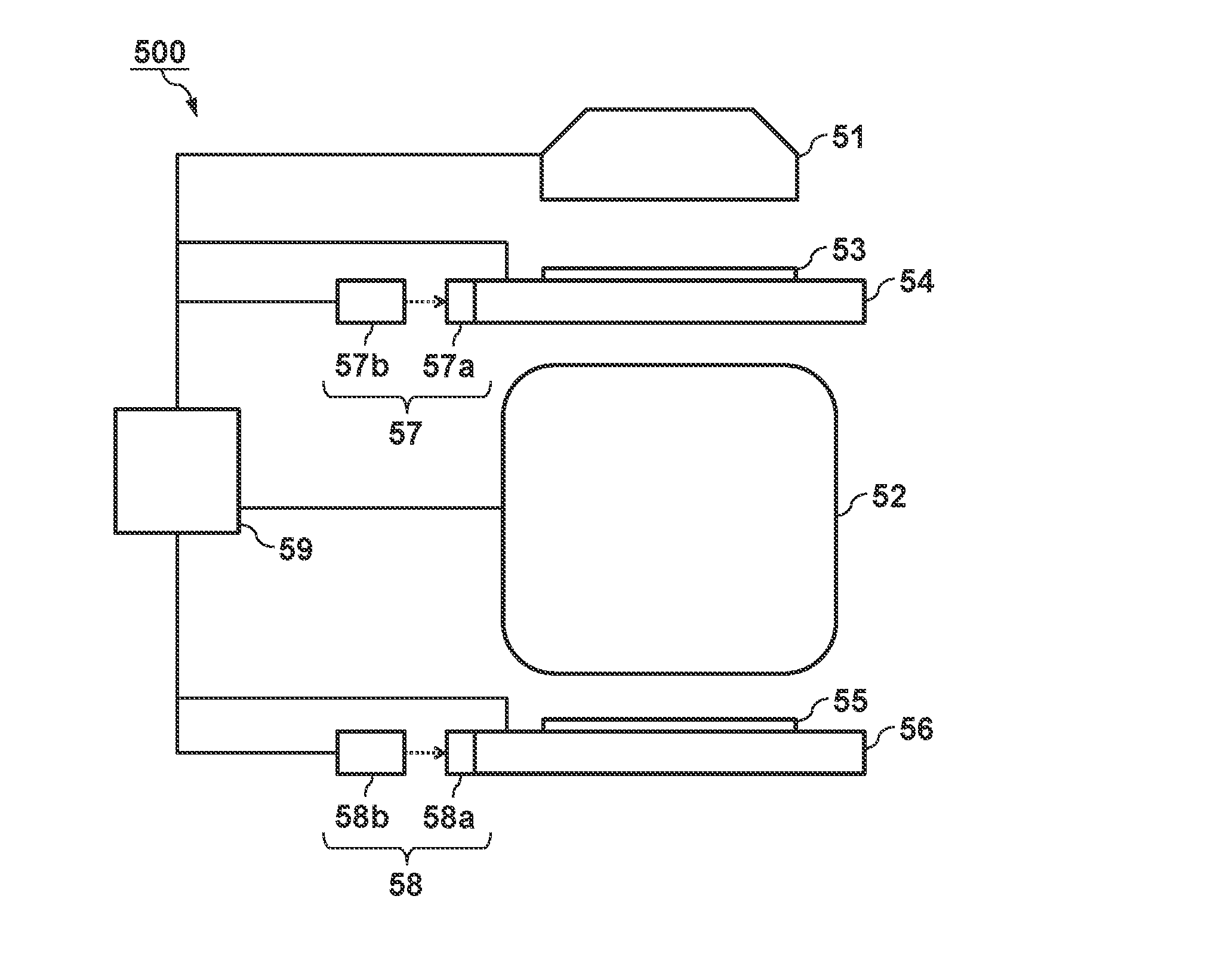
[0036]An example in which the measurement apparatus according to the above-described embodiment is applied to a lithography apparatus for forming a pattern on a substrate will be explained. The lithography apparatus can include, e.g., an exposure apparatus which transfers a pattern of an original onto a substrate by exposing the substrate, an i...


PUM

PropertyMeasurementUnit
displacementaaaaaaaaaa
angleaaaaaaaaaa
optical pathaaaaaaaaaa

Abstract

The present invention provides a measurement apparatus for measuring a position of an object, comprising a reflecting portion provided on the object and having a surface on which reflectors configured to retroreflect light are arrayed, an optical system configured to cause first light to be incident on the surface, receive second light as reflected light of the first light, cause third light generated from the second light to be incident on the surface, and receive fourth light as reflected light of the third light, and a processor configured to determine the position of the object based on a detection result of the forth light, wherein the optical system is configured such that a displacement between optical paths of the first light and the second light is corrected by a displacement between optical paths of the third light and the fourth light.

Description

BACKGROUND OF THE INVENTION[0001]Field of the Invention[0002]The present invention relates to a measurement apparatus for measuring the position of an object, a lithography apparatus, and a method of manufacturing an article.[0003]Description of the Related Art[0004]There is a measurement apparatus which measures the position of an object based on the results of detection of light reflected by a reflecting surface formed on the object, and light reflected by a reference surface. It may become difficult for this measurement apparatus to accurately measure the position of an object (reflecting surface) if the object moves and the position and angle of the optical path of light (reflected light) reflected by the reflecting surface change relative to the optical path of light (incident light) to be incident on the reflecting surface. Japanese Patent Laid-Open No. 2001-141413 has proposed a measurement apparatus which measures the position of an object by using a reflecting surface on wh...

Claims


Application Information

Patent Timeline
Patent Type & Authority Applications(United States)
IPC IPC(8): G03F7/20G01S7/481G01S17/06
CPCG03F7/70775G01S7/4811G01S17/06G01B9/02018G01B9/02019G01B9/02028G01B9/02058G01B9/02061G02B5/136G03F7/7085
Inventor OKUDA, HIROSHI
Owner CANON KK
Why Eureka
Try Eureka