Customized sectional sign assembly kit and method of using kit for constructon and installation of same

a sectional sign and kit technology, applied in the field of roadside and building signage, can solve the problems of insufficient satisfaction of new digital signs, time-consuming and labor-intensive retrofitting, and inability to remove older non-digital signs, and achieve the effect of convenient lifting and mounting

Inactive Publication Date: 2017-02-23
ADTI MEDIA
View PDF0 Cites 9 Cited by
  • Summary
  • Abstract
  • Description
  • Claims
  • Application Information

AI Technical Summary

Benefits of technology

[0013]In a second embodiment of the second aspect of the present invention, the sign section assembly includes at least one structural frame secured to at least one structural signage support; wherein the at least one structural signage support includes at least a pair of spaced apart vertical beams, each vertical beam having mounted thereto at least one mounting bracket for helping to support the sign section assembly to the signage mounting structure; wherein the at least one structural signage support further includes at least one sheeting member with upwardly extending side wall members to facilitate mounting of the at least one sheeting member between the at least a pair of spaced apart vertical beams; and wherein the at least one sheeting member is spaced a sufficient distance from a back-side of the at least one structural frame to help form a natural airflow chimney therebetween, the natural airflow chimney extending from a top-side of the at least one structural frame a bottom-side of the at least one structural frame to facilitate cooling the individual ones of the plurality of display modules removably latched within the corresponding individual ones of the display module receiving bays.
[0018]In a seventh embodiment of the second aspect of the present invention, each display module includes a front-facing portion and a rear facing portion, wherein the front facing portion is mounted within a corresponding one of the display module receiving bays to facilitate forming a portion of the display area of the electronic sign; and wherein the rear facing portion is mounted within the natural airflow chimney extending from the bottom-side of the at least one structural frame to the top-side of the at least one structural frame to facilitate cooling the individual ones of the plurality of display modules removably latched within the corresponding individual ones of the display module receiving bays.
[0020]In a ninth embodiment of the second aspect of the present invention, the sign section assembly includes at least two structural frames secured to at least one structural signage support; wherein the at least one structural signage support includes at least a pair of spaced apart vertical beams, each vertical beam having mounted thereto at least one mounting bracket for helping to support the sign section assembly to a signage mounting structure; wherein the at least one structural signage support further includes at least one sheeting member with a pair of upstanding side walls to facilitate mounting of the at least one sheeting member between the at least a pair of spaced apart vertical beam; and wherein the at least one sheeting member and the at least two structural frames cooperate when mounted to the at least one structural signage support to help form a natural airflow chimney therebetween, the chimney extending from a top-side of the sign section assembly to a bottom-side of the sign section assembly to facilitate cooling the individual ones of the plurality of display modules removably latched within the corresponding individual ones of the display module receiving bays.
[0023]In a third aspect of the present invention, an electronic sign generally comprises at least one sectional sign assembly loaded with a plurality of display modules, the at least one sectional sign assembly having at least one structural frame mounted to a signage support for facilitating providing the plurality of display modules with natural airflow cooling and for helping to facilitate the lifting and mounting of the at least one sectional sign assembly to a signage mounting structure.

Problems solved by technology

Retrofitting non-digital have proven to be expensive, time consuming and labor intensive.
Moreover, simply removing an older non-digital sign and replacing it with a new digital sign has not proven entirely satisfactory either since older installed, non-digital, panels represent substantial capital outlays making it financially difficult, if not impossible, to discard such panels arbitrarily for replacement with digital panels.

Method used


Image

  • Customized sectional sign assembly kit and method of using kit for constructon and installation of same
  • Customized sectional sign assembly kit and method of using kit for constructon and installation of same
  • Customized sectional sign assembly kit and method of using kit for constructon and installation of same

Examples


Embodiment Construction

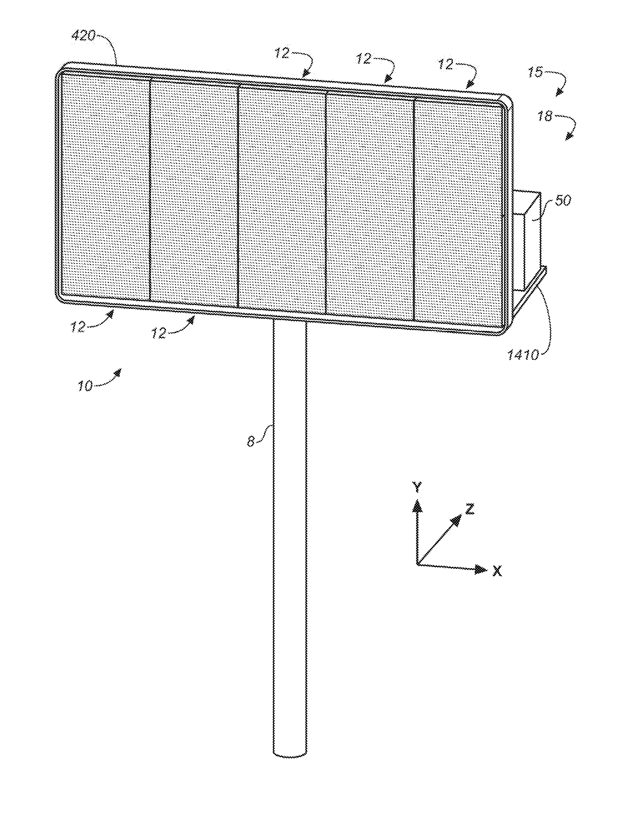
[0047]Referring now to the drawings and more particularly to FIGS. 1-7, there is illustrated a digital electronic sign 10 which is constructed in accordance with the present invention. The digital electronic sign 10 has a modular-like construction which may be customized as required by each sign installation site. The electronic sign 10 generally includes at least one pre-wired sectional sign assembly 12 which is configured to be electrically coupled to a power / data routing system 15. Each sectional sign assembly 12 is configured to be mounted to or supported by a conventional signage mounting structure, which may be an existing signage mounting structure or a newly installed signage mounting structure. In this regard, the signage mounting structures may include pole-like structures, such as a mounting pole structure 8 or a frame-like structure 1410 comprised of horizontal and vertical beams interconnected by angle irons and the like. Since these signage mounting structures are well...


PUM


Abstract

An electronic sign having at least one sectional sign assembly, the at least one sectional sign assembly having a signage support structure and an associated compound structural frame, wherein the compound structural frame has a unitary structural foam construction with a plurality of display module receiving bays, each configured for removably latching therein a plurality of display modules, the signage support structure and the associated compound structural frame cooperating when secured together to form a natural airflow cooling path extending from the top to the bottom of sectional sign assembly to provide sufficient cooling to the plurality of display modules when removably mounted within their display module receiving bays.

Description

RELATED APPLICATIONS[0001]This application is a continuation-in-part utility patent application claiming priority to U.S. patent Ser. No. 14 / 726,825, filed on Jun. 1, 2015, which is a divisional utility patent application of U.S. patent Ser. No. 14 / 242,654, filed on Apr. 1, 2014, now U.S. Pat. No. 9,047,791, issued on Jun. 2, 2015, which is a continuation-in-part of U.S. patent application Ser. No. 14 / 214,778, entitled “Sectional Sign Assembly and installation Kit and Method of Using Same”, by David Franklin Cox, et al. filed on Mar. 15, 2014, as a continuation-in-part of U.S. patent application Ser. No. 14 / 075,308, entitled Modular Installation and Conversion Kit for Electronic Sign Structure and Method of Using Same”, by David Franklin Cox, et al. filed on Nov. 8, 2013, now U.S. Pat. No. 8,824,125, which is a continuation-in-part patent application of U.S. patent application Ser. No. 14 / 056,017 entitled, “Modular Wire Harness Arrangements and Methods of Using Same for Back-side to...

Claims


Application Information

Patent Timeline
Patent Type & Authority Applications(United States)
IPC IPC(8): G09F9/302G09F9/33G09F27/00G09F7/18G09F15/00G09F19/22
CPCG09F9/3026G09F15/0037G09F19/22G09F2007/1804G09F27/008G09F7/18G09F9/33G09F19/228
Inventor COX, DAVID FRANKLINMARTINDALE, CHARLES ALLENCARLSON, ARNE E.
Owner ADTI MEDIA
Why Eureka
Try Eureka