Integrated magnetic component

a magnetic component and integrated technology, applied in the direction of electric variable regulation, process and machine control, instruments, etc., can solve the problems of affecting efficiency, dictating the size and electrical performance of the components, reliability and cost, and higher size and cost, so as to improve the power density, reduce losses, and negatively impact the effect of emi quality

Active Publication Date: 2017-02-23
DELTA ELECTRONICS (THAILAND) PUBLIC CO LTD
View PDF5 Cites 23 Cited by
  • Summary
  • Abstract
  • Description
  • Claims
  • Application Information

AI Technical Summary

Benefits of technology

[0007]It is the object of the invention to create an integrated magnetic component for switching power supplies pertaining to the technical field initially mentioned allowing to integrate more inductive components, having an improved power density and therefore having reduced losses, without negatively impacting the EMI quality.

Problems solved by technology

Switched mode power supplies as main parts of telecom and commercial systems often dictate their size and electrical performance as well as reliability and costs.
This converter results, additionally to the number of discrete magnetic components which yield higher size and costs, in at least three windings and several interconnections which negatively impact the efficiency.
Despite all the benefits of the LLC converter in terms of efficiency and EMI there are still some drawbacks.
However, this circuit implies even more discrete magnetic components and more interconnections which increase the volume drastically and damage the efficiency gains.
Also the above mentioned structure disclosed in US 2008 0224 809 is not suitable for such complex converters with more than one filter chokes and especially not for converter with split resonant chokes.
Distributing the inductive components over more than one magnetic component would not only minimize losses and increase the volume, but may also deteriorate the EMI quality.

Method used


Image

  • Integrated magnetic component
  • Integrated magnetic component
  • Integrated magnetic component

Examples


first embodiment

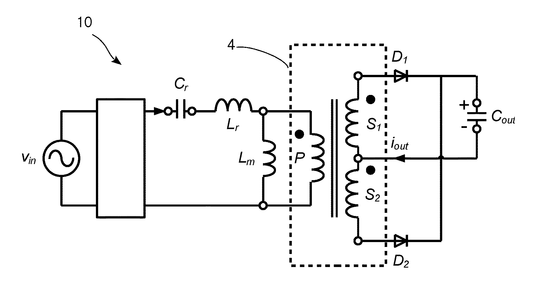
[0088]However, this circuit can be integrated by means of the integrated magnetic component 103 according to the invention.

[0089]In the following drawings similar elements of different embodiments are denoted by similar reference numerals differing by the hundreds digit if they are depicted in different drawings.

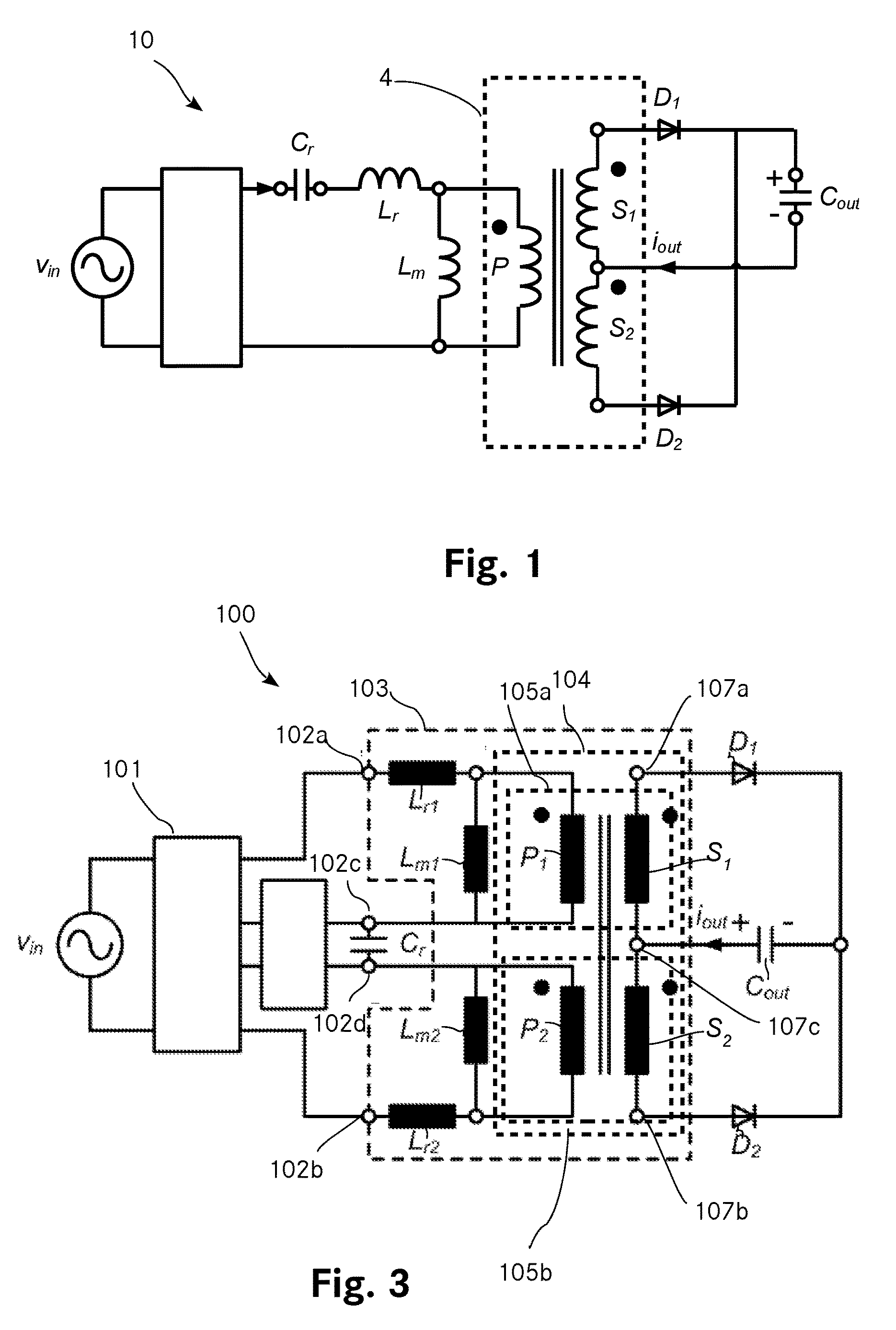
[0090]FIG. 3 shows an AC to DC converter 100 including a LLC converter unit 101 with a rectifying stage (not shown), and a full bridge (not shown) and a split resonant choke. The resonant LLC circuit with split resonant choke comprises a series resonant capacitor Cr, two series resonant inductors Lr1 and Lr2, two parallel resonant inductors Lm1 and Lm2 as well as a split transformer 104. All the five inductive components Lr1, Lr2, Lm1, Lm2, 104 are implemented on an integrated magnetic component 103 according to the invention. The split transformer 104 comprises a first transformer 105a with a first primary winding P1 and a first secondary winding S1, and a second transforme...

second embodiment

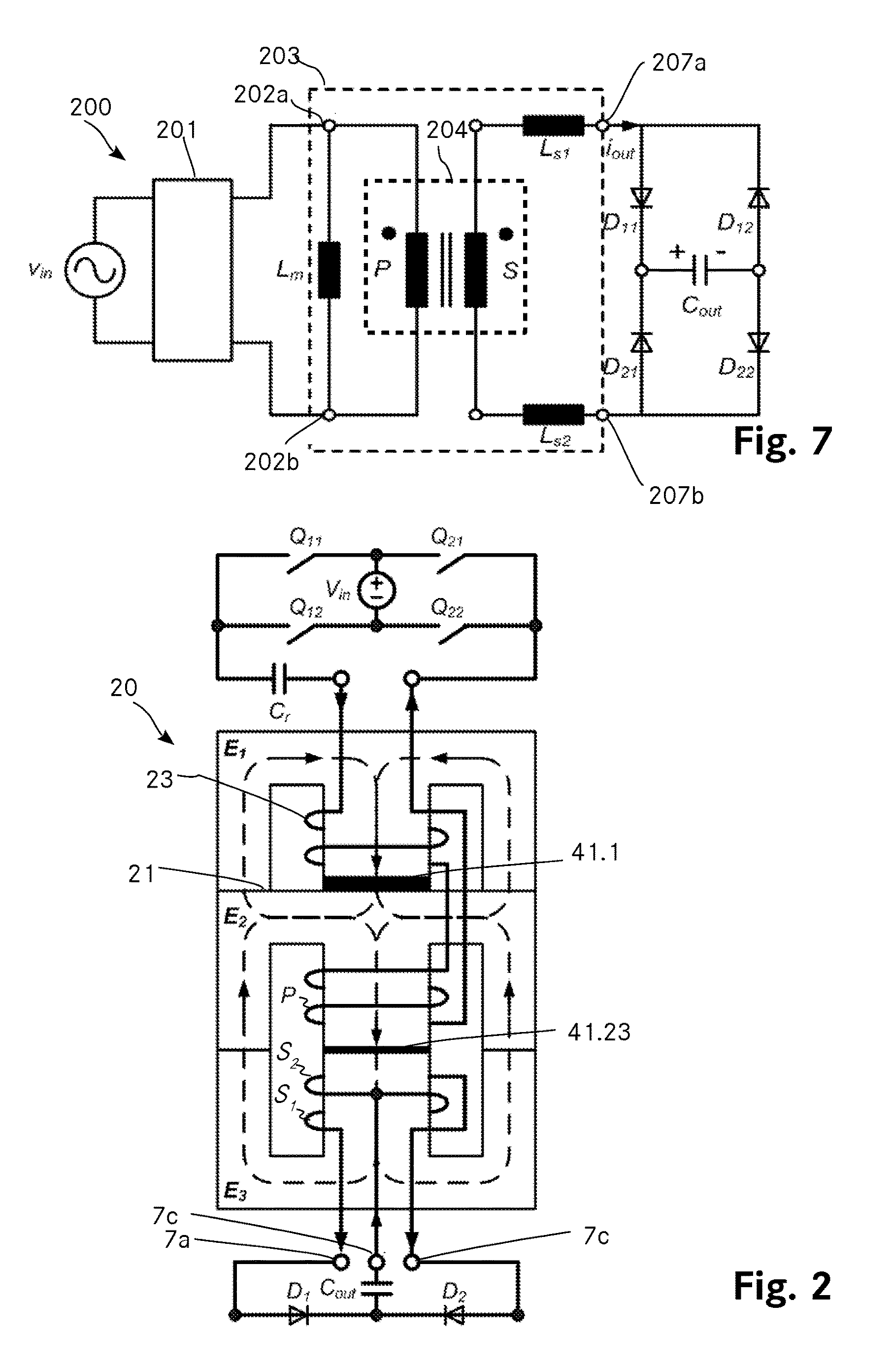
[0113]FIG. 7 shows an electrical diagram of an AC to DC converter 200 including a soft switching converter unit 201 and a soft switching circuit with two series output inductors Ls1 and Ls2, a parallel inductors Lm and a transformer 204. All those magnetic components are implemented by means of an integrated magnetic component 203 according to the invention. The electric circuit according to FIG. 7 comprises a soft switching converter unit 201 with two outputs (as for instance proposed in U.S. Pat. No. 6,862,195B). The outputs are connected to a first connection point 202a and a second connection point 202b of the integrated magnetic component 203 implementing the magnetic components of the soft switching circuit. The integrated magnetic component comprises a first load connection output 207a and a second load connection output 207b, for connecting an H-bridge full wave rectifier comprising four diodes D11, D12, D21, D22 and a filter capacitor Cout.

[0114]The integrated magnetic comp...

third embodiment

[0130]As depicted in FIG. 11, showing the integrated magnetic component 303 according to the invention, the air gaps can also be distributed along all three legs of any core. Distribution of the air gaps over the legs of the core elements reduces negative effects of air gap fringing fields and may also avoid grinding of the core elements, for instance be inserting a flat layer of a material with a low permeability.

[0131]This in contrast to the first embodiment of the integrated magnetic component 103 (FIG. 4) and the second embodiment of the integrated magnetic component 203 (FIG. 8), where the air gaps 141.1, 141.23, 141.4, 241.1, 241.23, 241.4 are single air gaps arranged in the centre legs (121.1, 121.2, 121.3, 121.4, 221.1, 221.2, 221.3, 221.4) of the core elements E1, E2, E3 and E4 which yields higher fringing fields.

[0132]The air gap in a flux path between the first / second choke core element E1 / E4 and the first / second transformer core element E2 / E3 is distributed over the thre...


PUM

PropertyMeasurementUnit
voltageaaaaaaaaaa
voltageaaaaaaaaaa
voltageaaaaaaaaaa

Abstract

The invention relates to an integrated magnetic component for a switched mode power converter, which includes a transformer with two transformer core elements (E2, E3) and at least one choke core element (E1, E4). Each core element (E1, E2, E3, E4) comprises two outer legs (120a, 120b) and a flange (122) which connects the outer legs (120a, 120b) to form U-like core elements. Each choke core element (E1, E4) abuts a flange (122) of one of the transformer core elements (E2, E3). The integrated magnetic component (103) includes a first choke winding (123) arranged on a leg (121.1) of a choke core element (E1) and a second choke winding (124) arranged on another leg (121.4) of a choke core element (E4), where one of a primary (P1, P2) or a secondary winding (S1, S2) of the transformer is connected between the choke windings (123, 124) and where all windings (P1, P2, S1, S2, 123, 124) are interconnected to reduce core losses by flux compensation in order to increase power density.

Description

TECHNICAL FIELD[0001]The invention relates to an integrated magnetic component for a switched mode power converter. The integrated magnetic component includes a transformer which comprises two transformer core elements. The integrated magnetic component also includes at least one choke core element. Each of said core elements comprises a first and a second outer leg and a flange which connects the outer legs to form U-like core elements. The transformer core elements are arranged to form an O-like core element. Each choke core element abuts a flange of one of the transformer core elements. The transformer further comprises a primary winding and a secondary winding which are arranged on a leg of the transformer core elements. In addition, the transformer includes a first air gap which is arranged in a flux path between the transformer core elements. The integrated magnetic component further includes at least a second air gap in a flux path between a transformer core element and a cho...

Claims


Application Information

Patent Timeline
Patent Type & Authority Applications(United States)
IPC IPC(8): H02M3/335H01F41/02H01F27/40H02M1/42H01F27/28
CPCH02M3/33546H02M1/42H01F41/02H01F27/40H01F27/2823H01F27/306H02M3/33573H02M3/01H02M3/003H02M7/068H02M1/0058H02M1/44H01F27/263H01F3/14H01F27/38H01F3/10H01F30/04H01F30/10Y02B70/10
Inventor NJIENDE T., HUGUES DOUGLASTIKHONOV, SERGEY
Owner DELTA ELECTRONICS (THAILAND) PUBLIC CO LTD
Why Eureka
Try Eureka