Integrated magnetic component and power converter

a technology of integrated magnetic components and power converters, which is applied in the direction of power electronics conversion, cores/yokes, and electric variable regulation, etc., can solve the problems of affecting efficiency, dictating the size and electrical performance as well as reliability and costs, and higher size and costs, so as to reduce overcall core size and copper losses, and improve power density. , the effect of reducing the effect of overcall core size and copper loss

Active Publication Date: 2018-11-08
DELTA ELECTRONICS (THAILAND) PUBLIC CO LTD
View PDF1 Cites 19 Cited by
  • Summary
  • Abstract
  • Description
  • Claims
  • Application Information

AI Technical Summary

Benefits of technology

[0011]It is the object of the invention to create an integrated magnetic component for a power converter including N>=2 LLC converters configured for interleaved operation pertaining to the technical fie

Problems solved by technology

Switched mode power supplies as main part of telecom and commercial systems often dictate their size and electrical performance as well as reliability and costs.
This converter results, additionally to the number of discrete magnetic components which yield higher size and costs, in at least six windings and several interconnections which negativel

Method used


Image

  • Integrated magnetic component and power converter
  • Integrated magnetic component and power converter
  • Integrated magnetic component and power converter

Examples


first embodiment

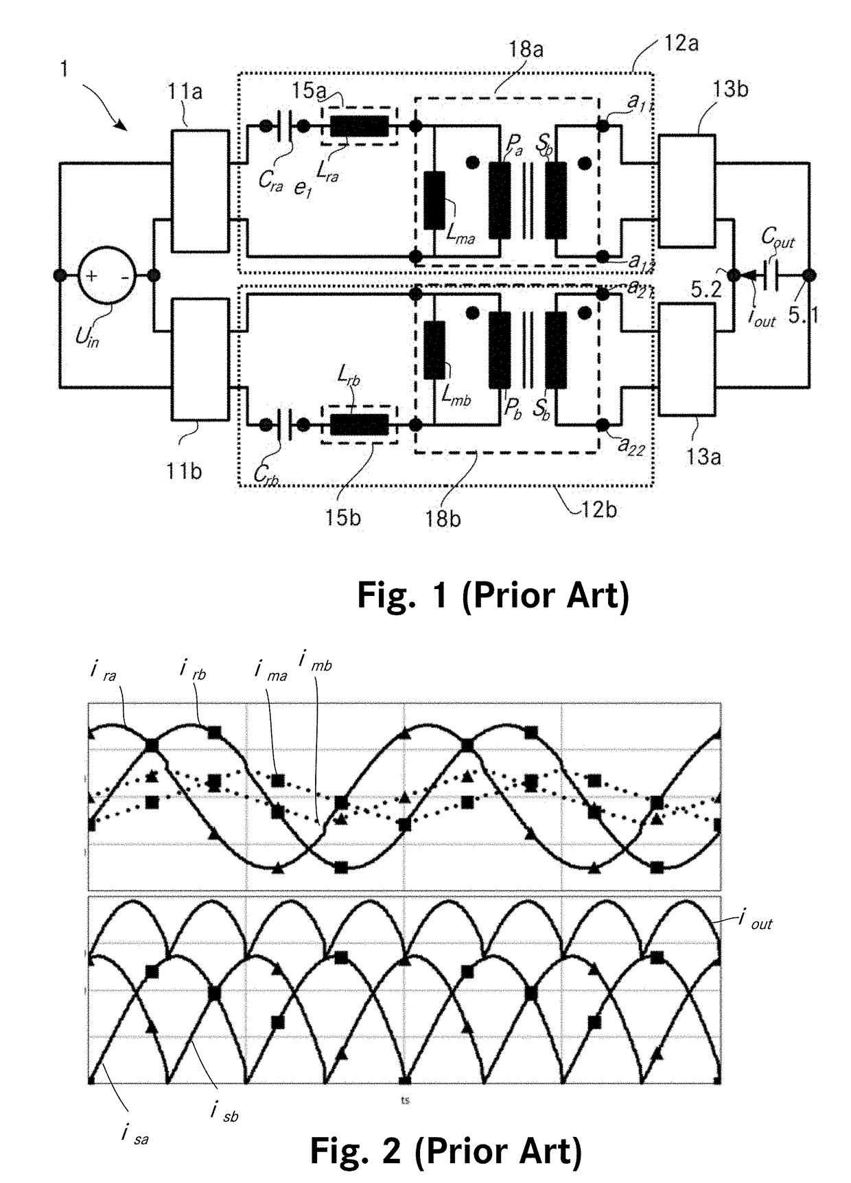
[0125]FIG. 5a shows the power converter 101 including the integrated magnetic component 102 according to the invention. The power converter 101 includes similarly to the power converter shown in FIGS. 3 and 4, two interleaved LLC resonant converters and can be modelled by means of the same equivalent circuit diagram shown in FIG. 1 as the prior art converters according to FIGS. 3 and 4. The power converter according to FIG. 5a however differs from prior art converters by its integrated magnetic component 102 which implements the magnetic components of the two interleaved magnetic LLC converters in a single magnetic core 130.

[0126]The power converter 101 includes besides the integrated magnetic component 102 a DC voltage input with a first and a second input terminal 104.1 and 104.2, for being connected to a DC voltage source Uin, and an output comprising a first and a second output terminal 105.1 and 105.2 for providing a DC output voltage.

[0127]The power converter further comprises...

second embodiment

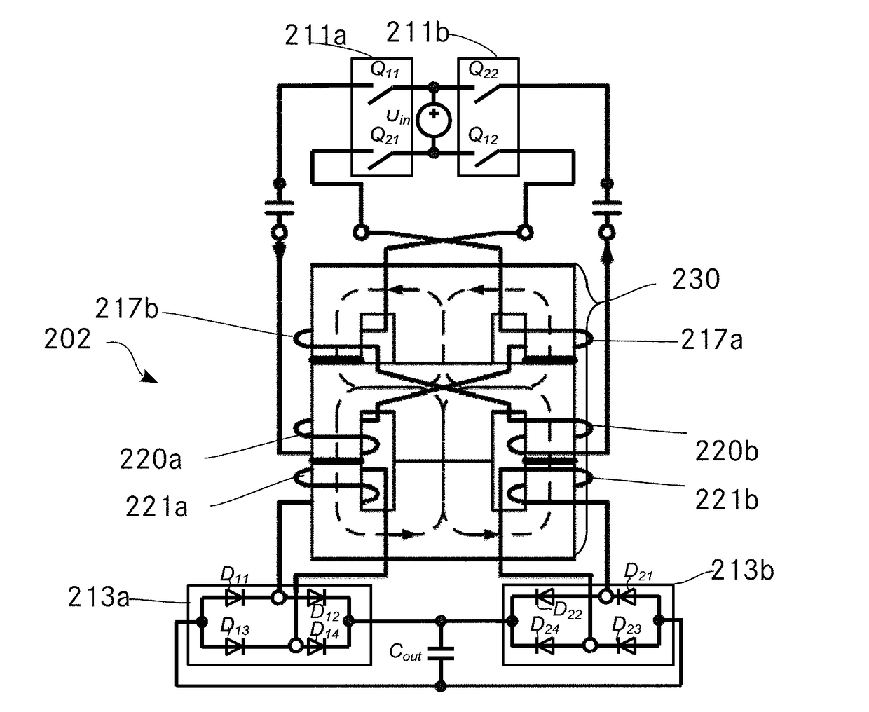
[0159]the power converter according to the invention shown in FIG. 8a is similar to the power converter shown in FIGS. 5a and 5b. The integrated magnetic component 202 of this embodiment of the invention has a similar magnetic core structure 230 as the magnetic core structure according to FIG. 5b. It also comprises a first switching converter 211a and a first output rectifier 213a for the first LLC converter and a second switching converter 211b and a second rectifier 213b for the second LLC converter. To reduce core losses however, the first choke winding 217a of the first LLC converter is wound on a winding carrying leg which is different from the winding carrying leg, where the first primary winding 220a and the second secondary winding 221a of the first LLC converter are wound, the winding of said first choke winding 217a and the winding of said first primary winding 220a being connected in series. Also, the second choke winding 217b of the second LLC converter is wound on a win...

third embodiment

[0174]FIG. 10a shows the power converter 601. It differs from the power converter 102 according to FIG. 5a, by its integrated magnetic component 602. The integrated magnetic component 602 also comprises four inputs and four outputs, namely a first input of the first LLC converter 603.1a, a second input for the first LLC converter 603.2a, a first input of the second LLC converter 603.1b and a second input of the second LLC converter 603.2b. It further comprises a first output of the first LLC converter 608.1a, a second output of the first LLC converter 608.2a, a first output of the second LLC converter 608.1b and a second output of the second LLC converter 608.2b.

[0175]The magnetic core structure 630 of the integrated magnetic component 602 is depicted separately in FIG. 10b. In comparison to the core structure 130 (FIG. 5b) of the integrated magnetic component 102, the magnetic core structure 630 comprises 4 E-cores, namely a first E-core 631, a second E-core 632, a third E-core 63...


PUM


Abstract

The invention relates to an integrated magnetic component (802) for a power converter including N>=2 LLC converters configured for interleaved operation. The integrated magnetic component (802) includes a first yoke and a second yoke and for each LLC converter a winding carrying leg which comprises a primary winding (820c) and a secondary winding (821c), wherein the primary winding (820c) and the secondary winding (821c) are wound on the respective winding carrying leg. The integrated magnetic component (802) further includes one or more return legs. Herein the winding carrying legs and the one or more return legs are arranged side by side, each leg being magnetically connected to both yokes and the winding carrying legs include a transformer air gap (819) whereas the at least one return leg is air gap free and at least one return leg is arranged between two winding carrying legs.
The invention further relates to a power converter including a switching converter stage (811a, 811b, 811c), a rectifier stage (813a, 813b, 813c) and a resonant stage, the resonant stage including N>=2 parallel LLC converters.

Description

TECHNICAL FIELD[0001]The invention relates to an integrated magnetic component for a power converter including N>=2 LLC converters configured for interleaved operation. The integrated magnetic component includes a first yoke and a second yoke and for each LLC converter a winding carrying leg which comprises a primary winding and a secondary winding, wherein the primary winding and the secondary winding are wound on the respective winding carrying leg. The integrated magnetic component further includes one or more return legs. Herein the winding carrying legs and the one or more return legs are arranged side by side, each leg being magnetically connected to both yokes and the winding carrying legs include a transformer air gap whereas the at least one return leg is air gap free.[0002]The invention further relates to a power converter including a switching converter stage, a rectifier stage and a resonant stage, the resonant stage including N>=2 parallel LLC converters.BACKGROUN...

Claims


Application Information

Patent Timeline
IPC IPC(8): H02M3/335H01F27/28H01F27/24
CPCH02M3/33569H01F27/2823H01F27/24H01F27/2828H02M3/33523H02M7/003H02M3/01H02M3/33573H01F3/14H02M3/285H01F27/38Y02B70/10H02M1/0058H02M1/0064
Inventor NJIENDE, HUGUES DOUGLASERINC, OSMANRUFF, DANIEL
Owner DELTA ELECTRONICS (THAILAND) PUBLIC CO LTD
Why Eureka
Try Eureka