Method and System for Compression of Radar Signals

a radar signal and compression technology, applied in the field of radar systems, can solve the problems of limiting the capabilities of radar transceivers, ics memory incurs undesirable increases in both die size and cost of ics, and the memory capacity is limited

Pending Publication Date: 2017-02-23
TEXAS INSTR INC
View PDF13 Cites 92 Cited by
  • Summary
  • Abstract
  • Description
  • Claims
  • Application Information

AI Technical Summary

Problems solved by technology

The amount of on-chip memory on radar transceiver integrated circuits (ICs) used in embedded FMCW radar systems constrains the amount of data that can be store...

Method used


Image

  • Method and System for Compression of Radar Signals
  • Method and System for Compression of Radar Signals
  • Method and System for Compression of Radar Signals

Examples


Embodiment Construction

[0025]Specific embodiments of the disclosure will now be described in detail with reference to the accompanying figures. Like elements in the various figures are denoted by like reference numerals for consistency.

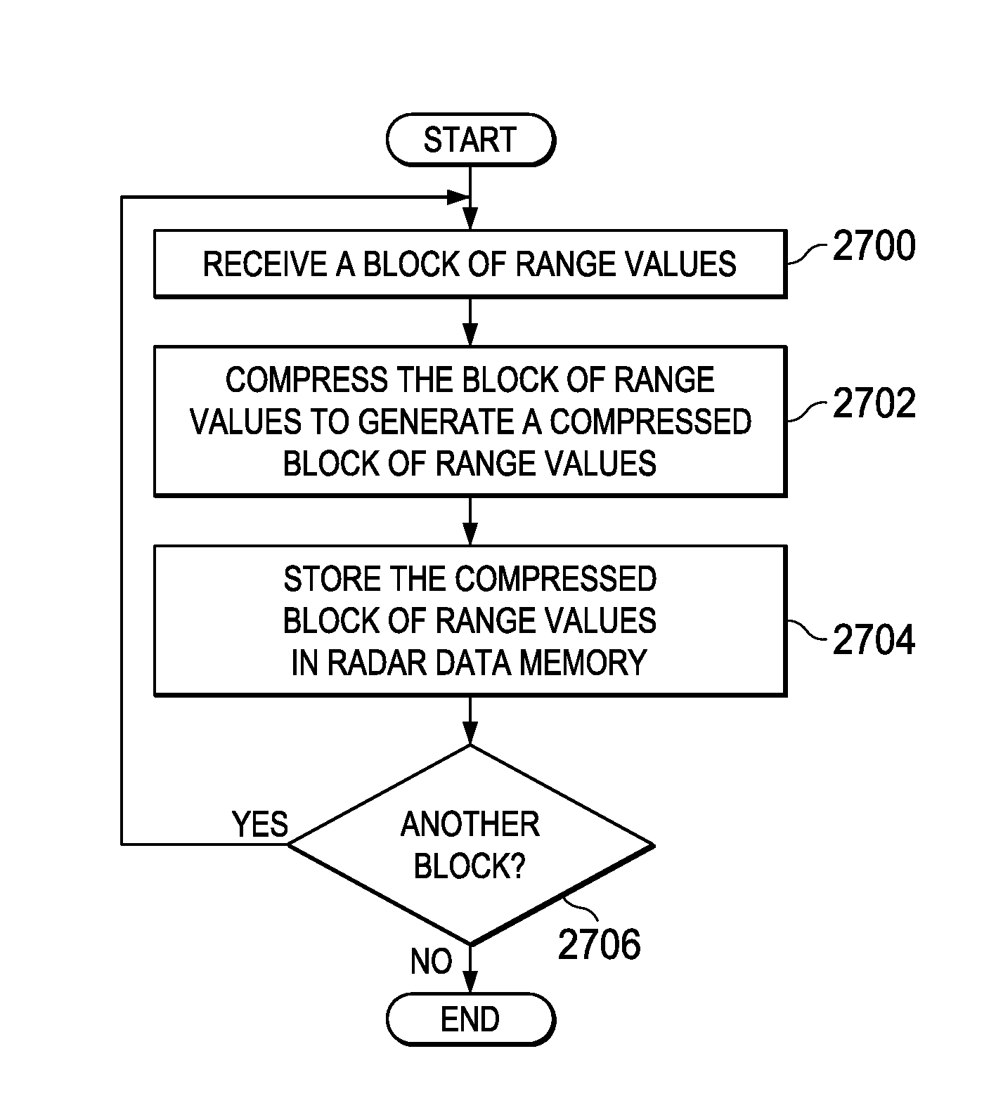
[0026]A Frequency Modulated Continuous Wave (FMCW) radar transmits, via one or more transmit antennas, a radio frequency (RF) frequency ramp referred to as a chirp. Further, multiple chirps may be transmitted in a unit referred to as a frame. The transmitted chirps are reflected from any objects in the field of view (FOV) the radar and are received by one or more receive antennas. The received signal for each receive antenna is down-converted to an intermediate frequency (IF) signal and then digitized. The digitized samples are pre-processed and stored in memory, which is referred to as radar data memory herein. Once the data for an entire frame is stored in the radar data memory, the data is post-processed to detect any objects in the FOV and to identify the range, velocit...


PUM


Abstract

A radar system is provided that includes a compression component configured to compress blocks of range values to generate compressed blocks of range values, and a radar data memory configured to store compressed blocks of range values generated by the compression component.

Description

CROSS-REFERENCE TO RELATED APPLICATIONS[0001]This application claims benefit of Indian Provisional Patent Application Serial No. 4339 / CHE / 2015 filed Aug. 19, 2015, which is incorporated herein by reference in its entirety.BACKGROUND OF THE DISCLOSURE[0002]Field of the Disclosure[0003]Embodiments of the present disclosure generally relate to radar systems, and more specifically relate to compression of radar signals in radar systems.[0004]Description of the Related Art[0005]The use of embedded Frequency Modulated Continuous Wave (FMCW) radar systems in applications such as automotive applications is evolving rapidly. For example, embedded FMCW radar systems may be used in a number of applications associated with a vehicle such as adaptive cruise control, collision warning, blind spot warning, lane change assist, parking assist and rear collision warning. Processing of radar signals in an FMCW radar system to obtain a three dimensional image (range, velocity, and angle) of objects in ...

Claims


Application Information

Patent Timeline
IPC IPC(8): H03M7/24G01S13/931
CPCH03M7/24H03M7/4075G01S13/18G01S13/34G01S13/931G01S7/295G01S13/343G01S13/584H03M7/40H03M7/4031G01S7/356G01S7/352
Inventor MANI, ANILRAO, SANDEEPRAMASUBRAMANIAN, KARTHIK
Owner TEXAS INSTR INC
Why Eureka
Try Eureka