Aircraft landing gear wheel-drive system

a technology of aircraft and gear, which is applied in the direction of aircraft braking system, braking arrangement, transportation and packaging, etc., can solve the problems of high fuel cost and ground level emissions, inefficient engine-thrust taxiing, and significant fuel burned by the engin

Active Publication Date: 2017-03-02
HONEYWELL INT INC
View PDF7 Cites 15 Cited by
  • Summary
  • Abstract
  • Description
  • Claims
  • Application Information

AI Technical Summary

Problems solved by technology

A significant amount of fuel may be burned by the engines during a typical aircraft taxi profile before and after each flight.
In that regard, engine-thrust taxiing may be considered inefficient and may contribute to high fuel costs and ground level emissions.
These design goals relating to a multiplicity of operational features often conflict with the design goal of constructing an ETS unit that is compact and light-weight.

Method used


Image

  • Aircraft landing gear wheel-drive system
  • Aircraft landing gear wheel-drive system
  • Aircraft landing gear wheel-drive system

Examples


Embodiment Construction

[0016]The following detailed description is of the best currently contemplated modes of carrying out the invention. The description is not to be taken in a limiting sense, but is made merely for the purpose of illustrating the general principles of the invention, since the scope of the invention is best defined by the appended claims.

[0017]Various inventive features are described below that can each be used independently of one another or in combination with other features.

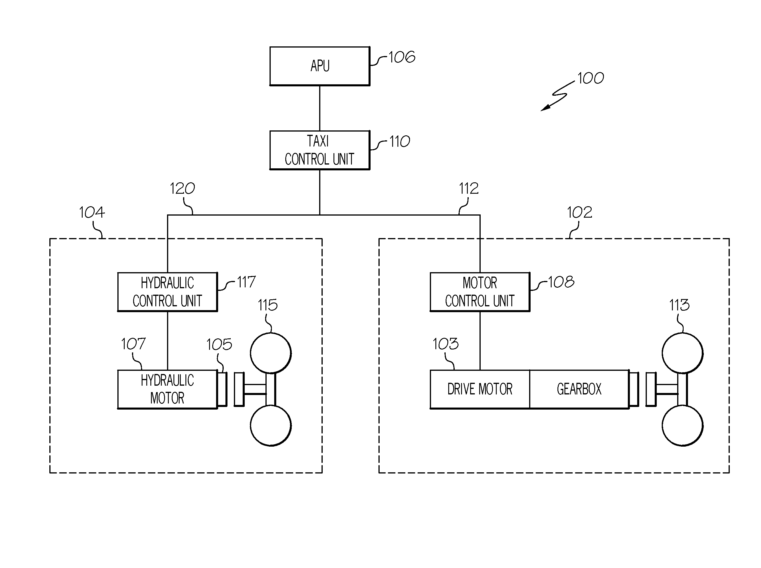
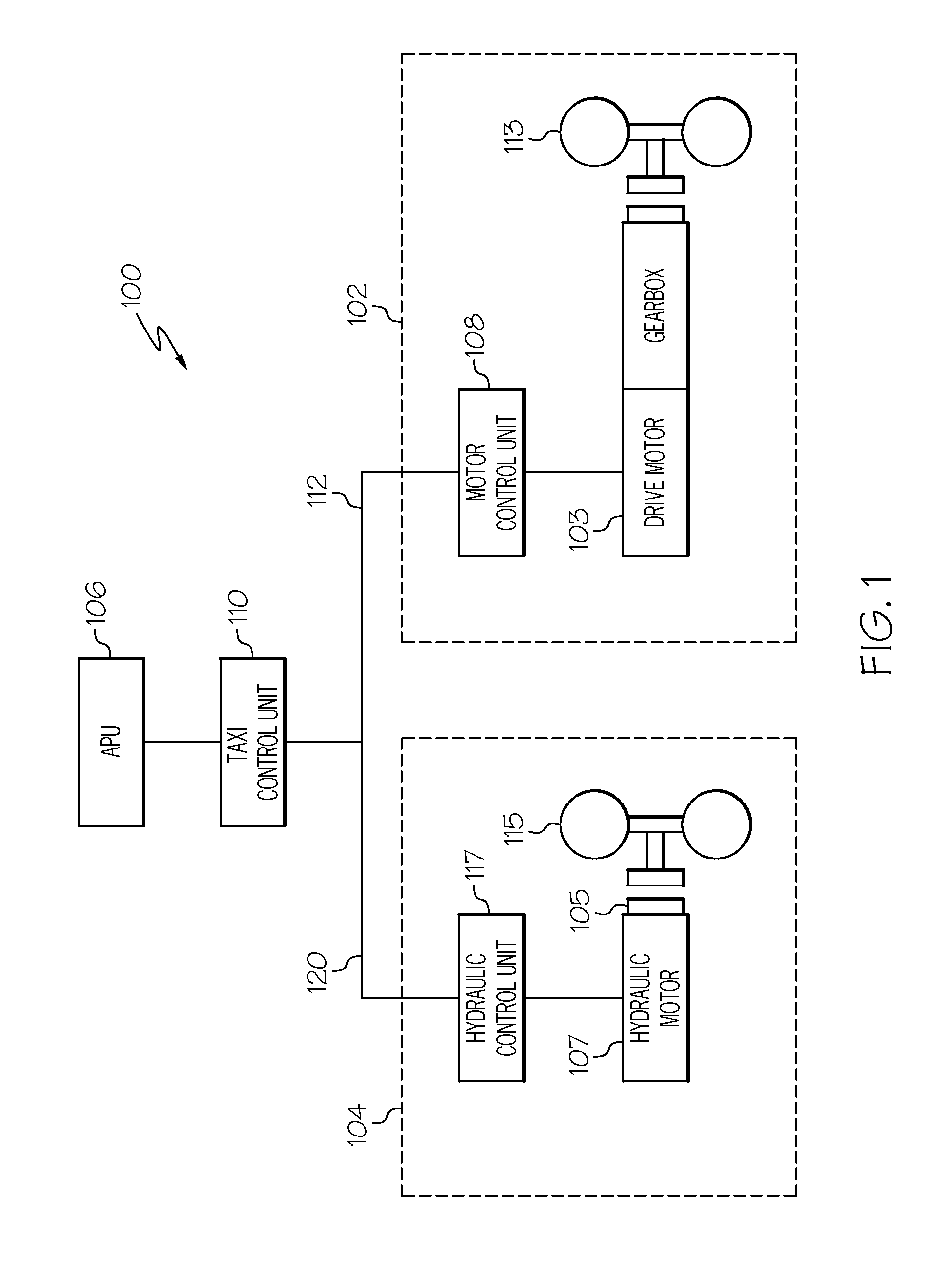
[0018]The present invention generally provides a landing gear wheel-drive system for an aircraft. The landing gear wheel-drive system may employ electric motors positioned to drive main-landing gear wheels. An additional motor may be positioned to drive nose-landing gear wheels. In other words, the landing gear wheel drive system may be considered to be a separated drive system. Advantageously, the nose wheels may be driven under conditions which demand high torque delivered at relatively low speed, e.g., push-bac...


PUM


Abstract

An aircraft landing gear wheel-drive system includes a first wheel drive unit for driving a first landing gear wheel of the aircraft and a second wheel drive unit for driving a second landing gear wheel of the aircraft. The first wheel drive unit has a first range of torque to speed (T / S) ratios. The second wheel drive unit has a second range of T / S ratios. The first range of T / S ratios is greater than the second range of T / S ratios.

Description

BACKGROUND OF THE INVENTION[0001]The present invention generally relates to aircraft landing gear. More particularly, the invention relates to landing gear with integrated drive systems to propel an aircraft during taxiing.[0002]A typical aircraft may taxi on to and from runways with thrust force developed by its engines. A significant amount of fuel may be burned by the engines during a typical aircraft taxi profile before and after each flight. In many cases, the main engines may provide more motive force than is required to complete a successful taxi profile. In that regard, engine-thrust taxiing may be considered inefficient and may contribute to high fuel costs and ground level emissions.[0003]Aircraft designers have sought a more efficient method for propelling an aircraft during taxiing. Electric taxi systems (ETS) have been proposed to provide higher efficiency. A typical ETS may be implemented by using electrical motors to drive main landing gear wheels for aircraft taxiing...

Claims


Application Information

Patent Timeline
Patent Type & Authority Applications(United States)
IPC IPC(8): B64C25/34B64C25/40B64C25/42
CPCB64C25/42B60W30/18127B60T2270/60B64C25/405B60T1/10B60T8/1703B60T10/04F16D57/06Y02T50/80B60K7/0007B60K7/0015
Inventor LO, CHARLESSTEVES, ALLAN
Owner HONEYWELL INT INC
Why Eureka
Try Eureka