

System and method for dynamically adjusting dryer belt speed
a technology of dynamic adjustment and dryer belt, which is applied in the direction of drying machines, drying machines with progressive movements, lighting and heating apparatus, etc., can solve the problems of rinsing the (expensive) belt, and achieve the effect of optimizing performance, efficiently and quickly changing the temperature of the dryer
- Summary
- Abstract
- Description
- Claims
- Application Information
AI Technical Summary
Benefits of technology
Problems solved by technology
Method used
Image

Examples
Embodiment Construction
[0028]While this invention is susceptible of embodiments in many different forms, there is shown in the drawings, and will herein be described in detail preferred embodiments of the invention with the understanding that the present disclosure is to be considered as an exemplification of the principles of the invention and is not intended to limit the broad aspect of the invention to the embodiments illustrated.
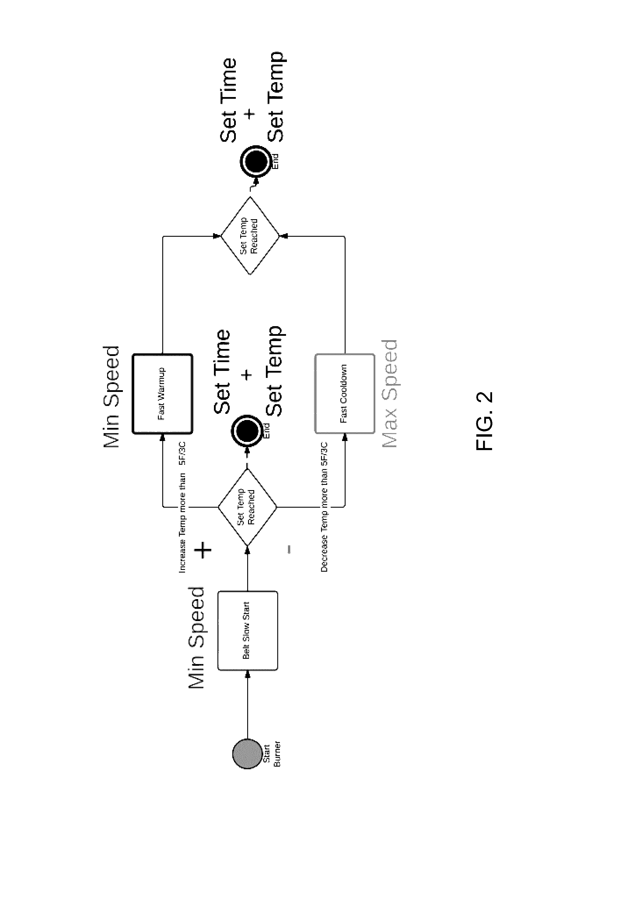
[0029]The present invention is directed to a textile dryer and method of operation for optimally heating and cooling a drying chamber by modifying the speed of a conveyor belt. Modification of the belt speed adjusts the amount of heat exhausted from the system.
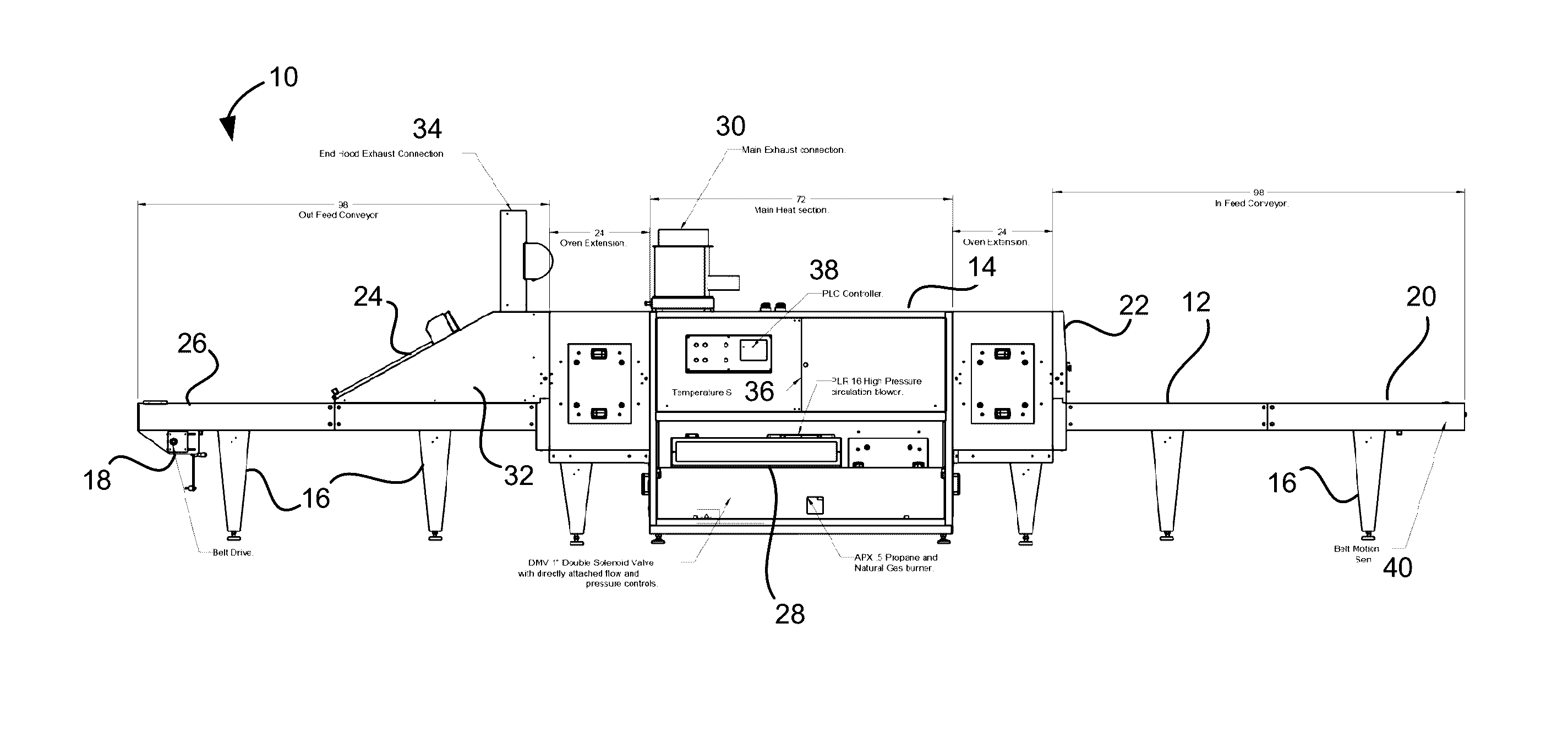
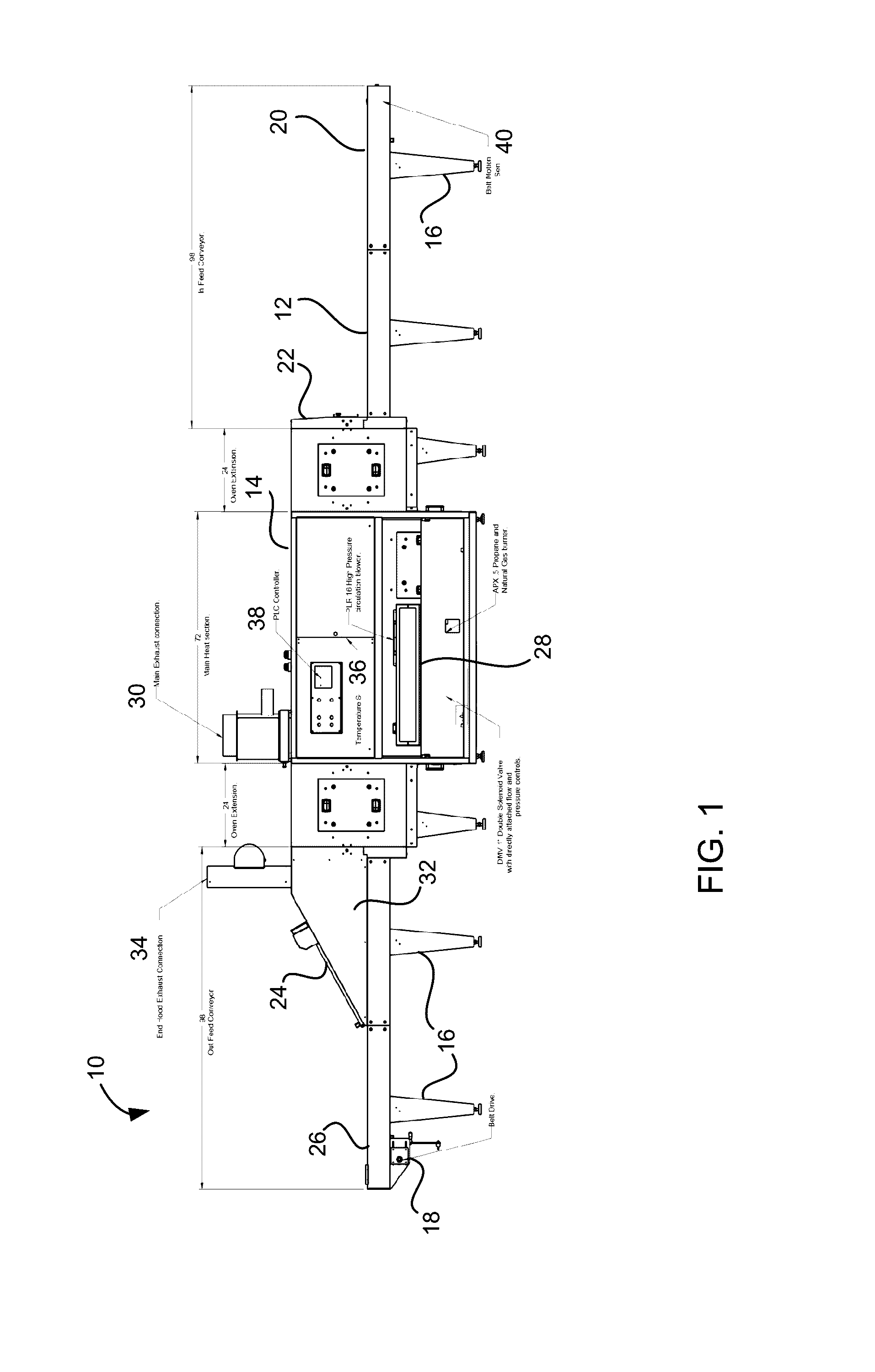
[0030]FIG. 1 shows a textile dryer 10 having a conveyor belt 12 that is used to advance textiles through a drying or heated chamber 14. The belt 12 and drying chamber 14 are supported by legs 16.
[0031]The belt 12 is part of an endless loop that is moved by a belt drive 18. Textiles are placed on the belt 12 at a first en...
PUM
 Abstract
Description
Claims
Application Information