Optical structure with ridges arranged at the same and method for producing the same

a technology of optical structure and ridges, applied in the direction of optics, mountings, instruments, etc., can solve the problems of individual parts and inability to produce in wafer level technology

Active Publication Date: 2017-03-02
FRAUNHOFER GESELLSCHAFT ZUR FOERDERUNG DER ANGEWANDTEN FORSCHUNG EV
View PDF7 Cites 6 Cited by
  • Summary
  • Abstract
  • Description
  • Claims
  • Application Information

AI Technical Summary

Benefits of technology

[0010]According to a first aspect of embodiments described below, an optical apparatus is provided which is able to counteract variations of optical characteristics caused by temperature variations in a self-regulating manner and independent of further actuators. Apparatuses can be miniaturized and can be produced in wafer level technology, so that a smaller construction size and / or lower production costs can be obtained. According to this aspect, apparatuses can, for example, compensate production tolerances and / or can allow variable focusing during operation of the optical overall system by inducing heat, so that further focusing mechanical members are substituted.
[0011]According to the first aspect, an apparatus includes an optical structure having at least two ridges that are implemented to allow a movement of the optical structure with regard to a reference plane. According to the first aspect, a method includes the implementation of ridges such that the same allow a movement of an optical structure arranged at the same, which counteracts a thermally induced variation of the optical characteristic of the optical structure.
[0013]According to an embodiment, the ridges are structured in a single-layered manner. In this case, the ridges can consist of the same material as the optical structure suspended from the ridges, allowing a simplified production. The material can have a higher coefficient of thermal expansion than the supporting structure surrounding the optical structure, which leads, during a temperature increase, to a movement of the optical structure in a direction along the optical axis. The direction of movement of the optical structure is defined by a curvature of the ridges lying in the plane in which the optical axis of the optical structure lies.
[0015]According to an embodiment, the longitudinal center lines of the ridges intersect the optical axis of the optical structure and the ridges are connected to the optical structure at the end. According to an alternative embodiment, the longitudinal center lines of the ridges do not intersect the optical axis of the structure and the ridges are laterally connected to the optical structure via protrusions. The latter example allows a larger longitudinal extension of the ridges and hence the enlargement of the obtainable travel range of the optical structure.
[0017]A second aspect of embodiments described below relates to a concept which enables maintaining an initial position of an optical structure after performed adjustment to become easier, for example without arranging threads or introducing allocated further mechanical components in housing structures, so that the termination of the adjustment, for example during production, is made easier.
[0020]A third and fourth aspect of embodiments described below solve the object of providing a concept for optical apparatuses which is able to induce movements into an optical structure connected to a frame via ridges independent of the environmental temperature and with high dynamics, wherein the actuators used for this are miniaturized and can be produced in wafer level technology, so that a smaller structural size and / or lower production costs can be obtained. According to these aspects, apparatuses can compensate, for example, production tolerances and / or can allow a variable focusing during operation of the optical overall system.

Problems solved by technology

However, these methods necessitate active adjustment of the focal length of the optical system.
The same consist of many individual parts and cannot be produced in wafer level technology.

Method used


Image

  • Optical structure with ridges arranged at the same and method for producing the same
  • Optical structure with ridges arranged at the same and method for producing the same
  • Optical structure with ridges arranged at the same and method for producing the same

Examples


Embodiment Construction

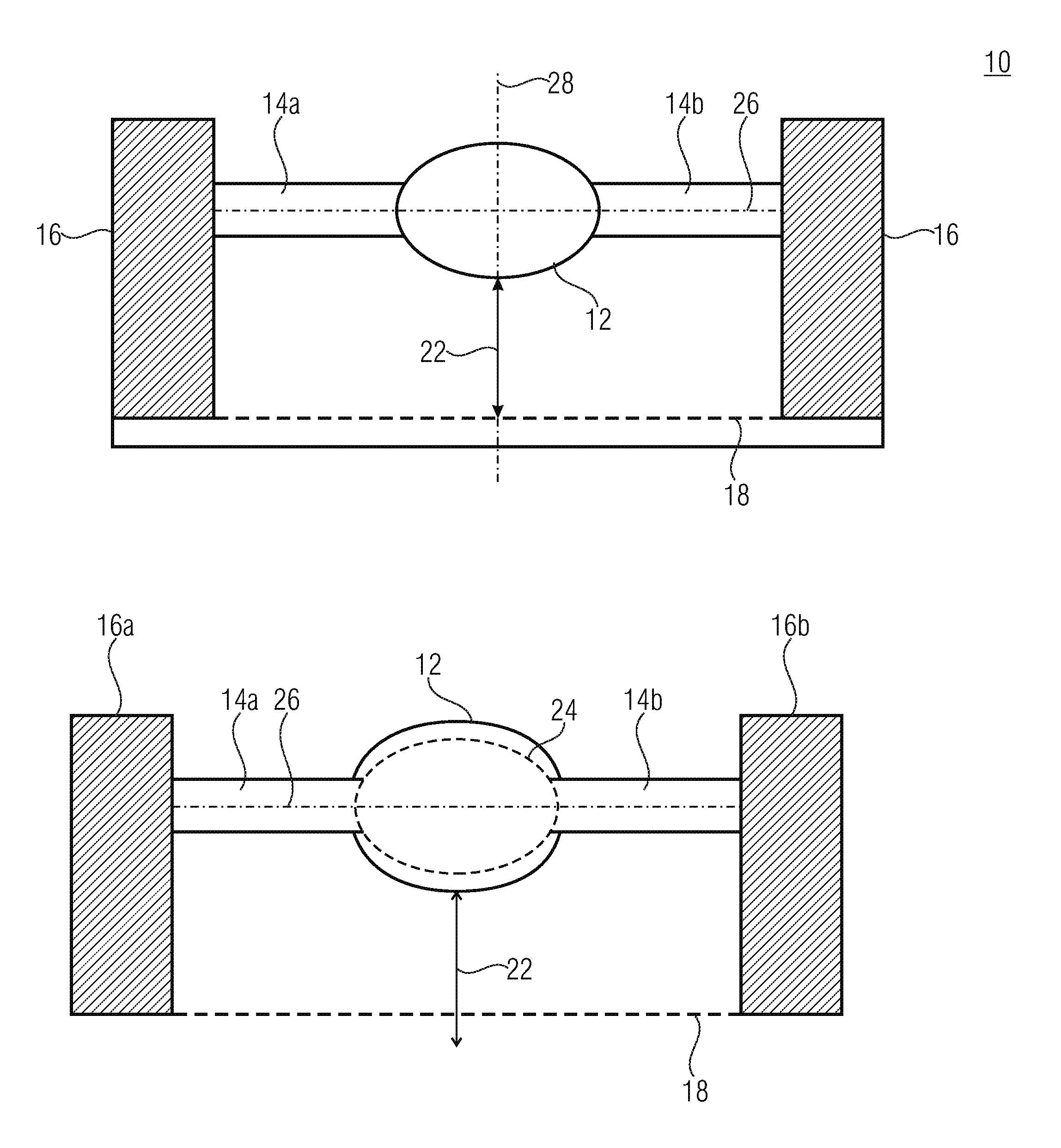
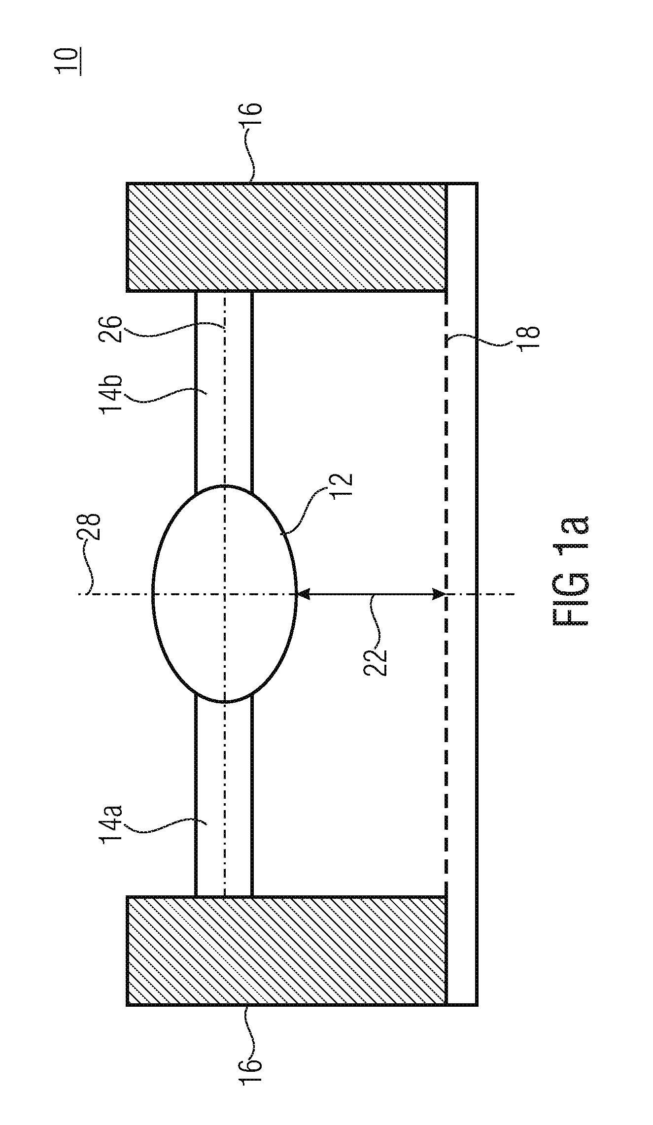
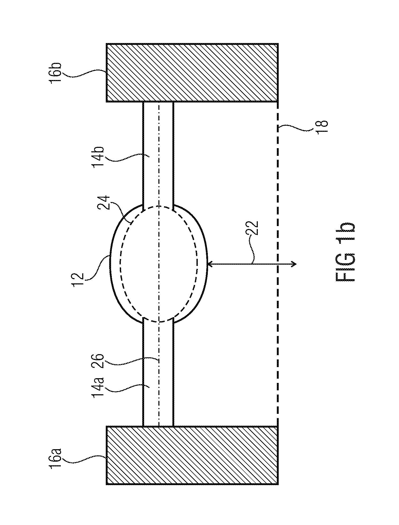
[0166]FIG. 1a shows a cross-sectional view of an apparatus 10 according to an embodiment of the invention. The apparatus includes a lens 12 mounted on a supporting structure 16, for example a frame, via two ridges 14a and 14b and arranged at a distance 22 to a reference plane 18 shown schematically in FIG. 1. The lens 12 and the ridges 14a and 14b are arranged in a common position plane 26. The reference plane 18 can, for example, represent an image plane where the image sensor comprised by the apparatus 10 is arranged. The distance 22 is selected according to the focal length of the lens 12. The ridges 14 are structured in a single-layered manner of a material including a greater coefficient of thermal expansion than the supporting structure 16. In case of a temperature increase, the ridges consequently expand particularly along the direction from the supporting structure 16 towards the lens 12 more than the supporting structure and can hence effect a deflection of the lens from th...


PUM


Abstract

An apparatus having an optical structure and ridges is described, wherein adhesive is arranged between the ridges and the optical structure, wherein the adhesive is effective to effect, after its annealing, a predetermined orientation of the optical structure in relation to a reference plane.

Description

CROSS-REFERENCE TO RELATED APPLICATIONS[0001]This application is a continuation of copending International Application No. PCT / EP2014 / 059610, filed May 12, 2014, which is incorporated herein by reference in its entirety, and additionally claims priority from German Application No. 10 2013 209 819.7, filed May 27, 2013, which is also incorporated herein by reference in its entirety.BACKGROUND OF THE INVENTION[0002]The present invention relates to an apparatus having an optical structure and ridges connecting the optical structure to a supporting structure, wherein the optical structure is able to perform a movement with regard to a reference plane, and the invention also describes possible adjustments for the apparatus.[0003]Optical structures made of curable material, as are known, for example, from DE 102009055080 A1, change their characteristics with varying environmental temperatures. Thus, a polymer lens changes its extension with varying temperature, such that the refractive in...

Claims


Application Information

Patent Timeline
Patent Type & Authority Applications(United States)
IPC IPC(8): G02B7/02G02B7/00G02B7/182G02B7/08G02B7/18
CPCG02B7/028G02B7/08G02B7/008G02B7/181G02B7/182G02B7/025G02B26/08G02B26/0866
Inventor WIPPERMANN, FRANKREIMANN, ANDREASBRAEUER, ANDREAS
Owner FRAUNHOFER GESELLSCHAFT ZUR FOERDERUNG DER ANGEWANDTEN FORSCHUNG EV
Why Eureka
Try Eureka