Eureka AIR delivers breakthrough ideas for toughest innovation challenges, trusted by R&D personnel around the world.

Optical system for head mount display

Inactive Publication Date: 2017-03-02
LEE JUN HEE
View PDF2 Cites 18 Cited by
  • Summary
  • Abstract
  • Description
  • Claims
  • Application Information

AI Technical Summary

Benefits of technology

The patent describes an optical system for a head mount display that can create a realistic and immersive experience for the user. It does this by directing the screen in front of the user's eyes in a way that makes it feel like they are wearing normal glasses. Additionally, the system can use 3D visual elements to create a more realistic and intricate augmented reality.

Problems solved by technology

The conventional optical system for a head mount display has a large volume due to the near beam splitter around the display and the beam splitter around the field of view of the user as a whole, and the optical pipe that connects the two elements also has a large volume, which causes an inconvenience problem.
Further, the conventional optical system for a head mount display has to always provide a fixed screen and a fixed field of view and to actually move the eyes of the wearer to secure a screen and a focus, which also causes an inconvenience problem.
Further, according to the conventional optical system for a head mount display, because a focus cannot be secured if the length of the optical pipe is reduced to reduce the volume thereof and the length of the optical system has to be about two times as larger as a general distance between the eyes of the user and the eyeglass lens, the mobility of the optical system cannot be secured.
For example, the focus may be disturbed even though the optical system is shaken to a degree.

Method used


Image

  • Optical system for head mount display
  • Optical system for head mount display
  • Optical system for head mount display

Examples


Embodiment Construction

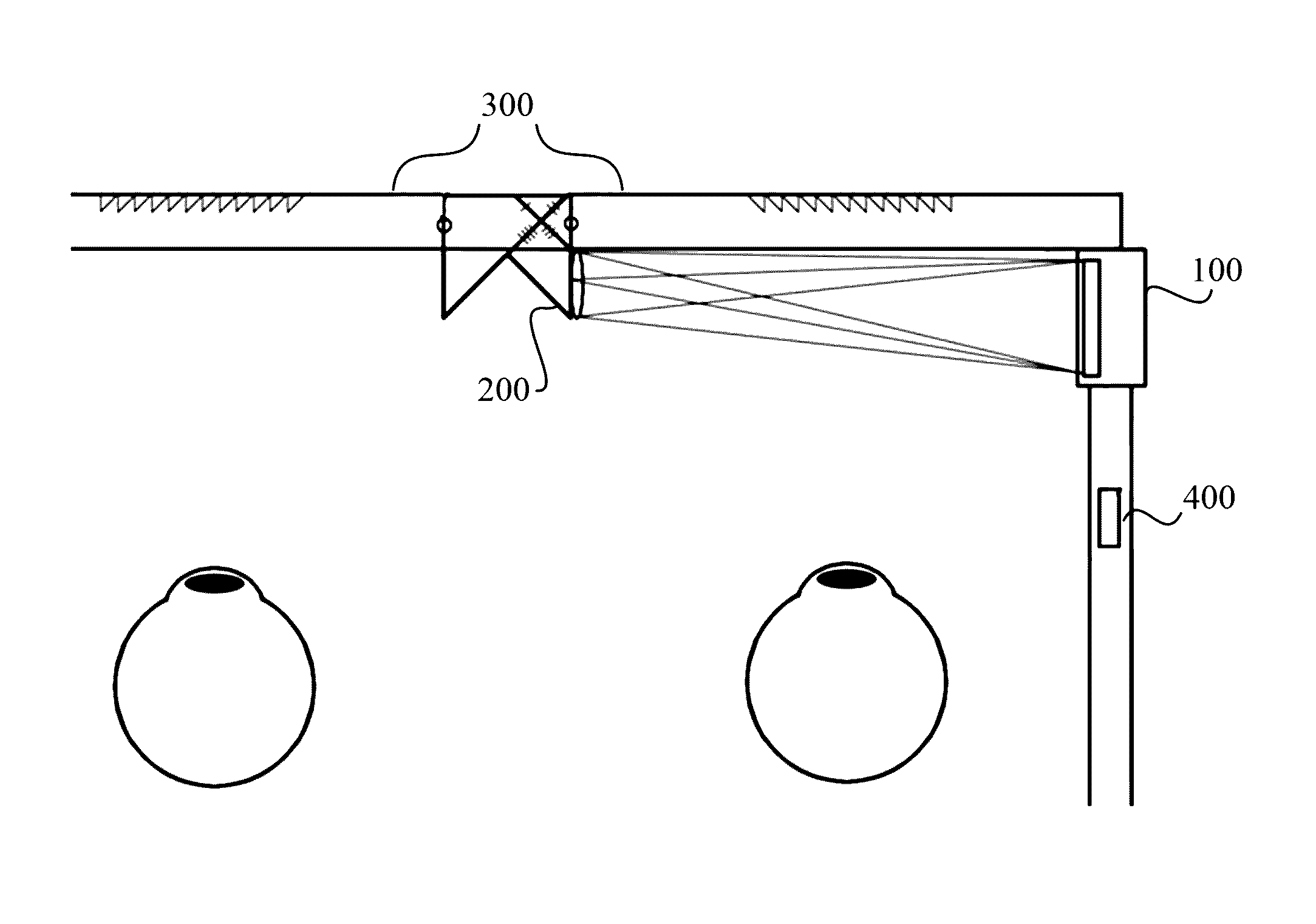
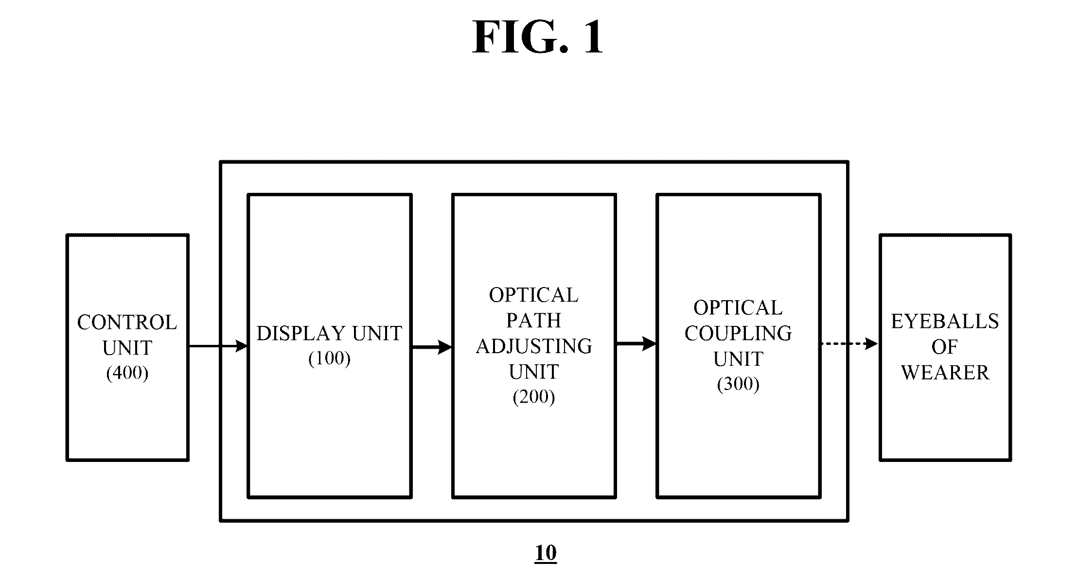
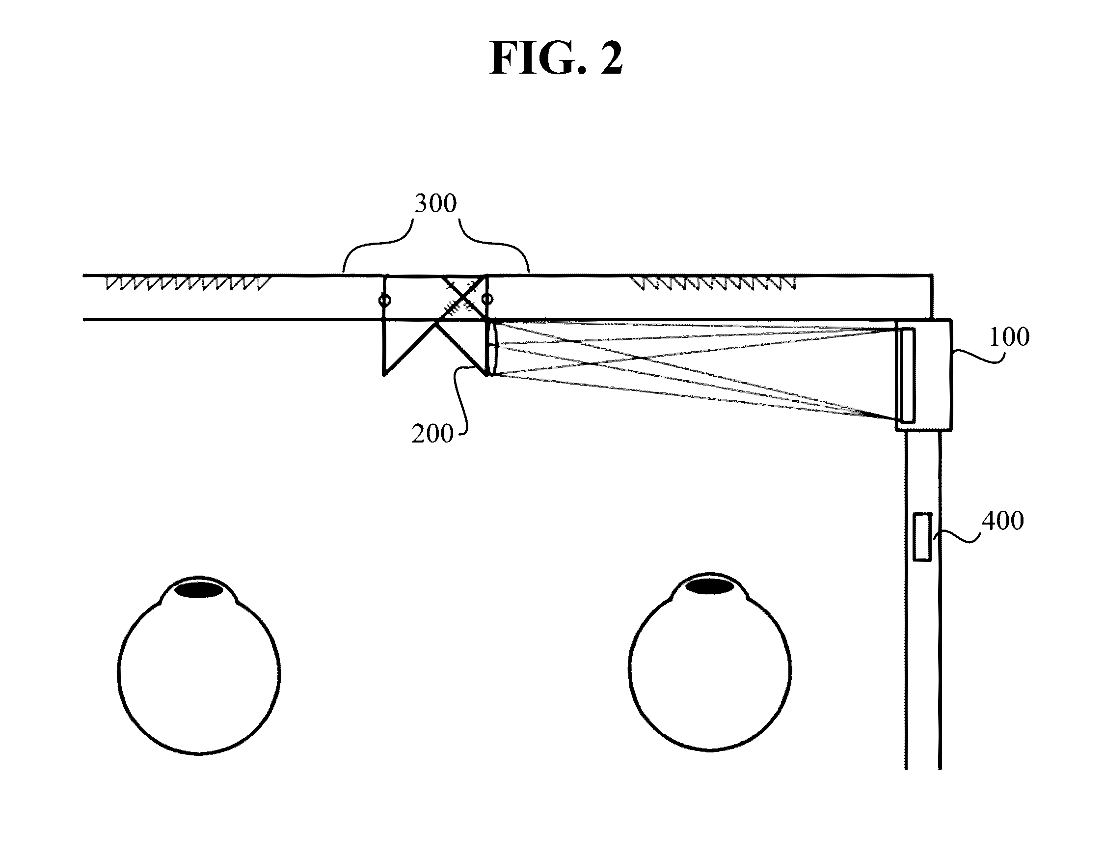
[0026]Hereinafter, exemplary embodiments of the inventive concept will be described in detail with reference to the accompanying drawings. The above and other aspects, features and advantages of the invention will become apparent from the following description of the following embodiments given in conjunction with the accompanying drawings. However, the inventive concept is not limited to the embodiments disclosed below, but may be implemented in various forms. The embodiments of the inventive concept is provided to make the disclosure of the inventive concept complete and fully inform those skilled in the art to which the inventive concept pertains of the scope of the inventive concept. The same reference numerals denote the same elements throughout the specification.

[0027]Unless otherwise defined, all terms (including technical and scientific terms) used herein have the same meaning as commonly understood by those skilled in the art to which the inventive concept pertains. It will...


PUM


Abstract

Disclosed is an optical system for a head mount display, including at least a display unit that is provided on an inner surface of a leg area of an eyeglass frame to provide virtual screen light, an optical path adjusting unit that is provided on a nose support area of the eyeglass frame to convert a direction of the virtual screen light delivered from the display unit by refracting or reflecting the virtual screen light, and an optical coupling unit that is provided in an interior of an eyeglass lens or at a location that is adjacent to the eyeglass lens to combine a virtual screen and a reality screen that is introduced from the outside and deliver the combined screen to the eyes of a wearer.

Description

CROSS-REFERENCE TO RELATED APPLICATIONS[0001]The present application is a continuation of International Patent Application No. PCT / KR2015 / 004924, filed May 15, 2015, which is based upon and claims the benefit of priority to Korea Patent Application No. 10-2014-0058293, filed on May 15, 2014. The disclosures of the above-listed applications are hereby incorporated by reference herein in their entirety.BACKGROUND[0002]Embodiments of the inventive concept described herein relate to an optical system for a head mount display.[0003]An optical system for a head mount display refers to an optical system for implementing a device configured to allow a user to view a 3D image through a liquid crystal screen that approaches the two eyes of the user.[0004]Korean Patent Application Publication No. 2014-0036351 (entitled “Compact See-through Display System” and published on Mar. 25, 2014 (Google Inc.)) discloses a configuration of an existing optical system for a head mount display. The existing...

Claims


Application Information

Patent Timeline
IPC IPC(8): G02B27/01G02B27/22G02C11/00G02B27/26G02B30/25
CPCG02B27/0172G02B27/26G02B2027/0134G02C11/10G02B2027/0178G02B27/2264G02B26/0875G02B27/02G02B27/026G02B30/24G02B30/25
Inventor LEE, JUN HEE
Owner LEE JUN HEE
Why Eureka
Eureka Blog
Learn More