Mirror display

Active Publication Date: 2017-03-02
SHARP KK
View PDF3 Cites 4 Cited by
  • Summary
  • Abstract
  • Description
  • Claims
  • Application Information

AI Technical Summary

Benefits of technology

[0011]The present invention can provide a mirror display that can suppress warp of a half mirror plat

Problems solved by technology

In such a mirror display, when a reflective polarizer is bonded to a polarizer disposed on the viewing surface side of a liquid crystal displa

Method used


Image

  • Mirror display
  • Mirror display
  • Mirror display

Examples


Example

Example 1

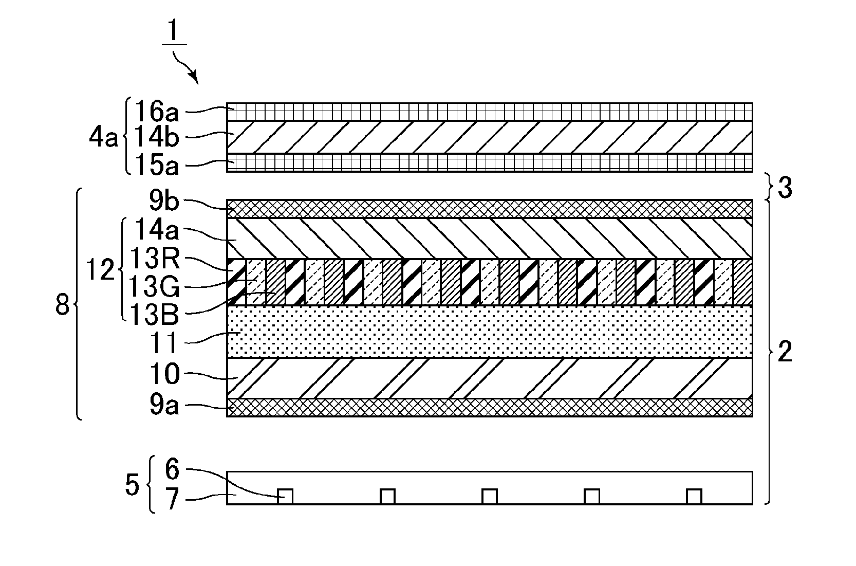
[0025]Example 1 relates to a mirror display that includes a liquid crystal display device, a reflective polarizer as a half mirror layer, and a heat-shrinkable member as a warp-suppressing member.

[0026]FIG. 1 is a schematic cross-sectional view of a mirror display of Example 1. As shown in FIG. 1, a mirror display 1 includes, in the order from the back surface side toward the viewing surface side, a liquid crystal display device 2, an air layer 3, and a half mirror plate 4a. The liquid crystal display device 2 and the half mirror plate 4a were fixed by fitting the upper and lower edges of the half mirror plate 4a to a pair of aluminum rails which are attached to the upper and lower edges of the liquid crystal display device 2 so as to form a frame-like structure. The air layer 3 is the space formed in a slight gap between the liquid crystal display device 2 and the half mirror plate 4a. The term “viewing surface” as used herein refers to the surface of the mirror display on...

Example

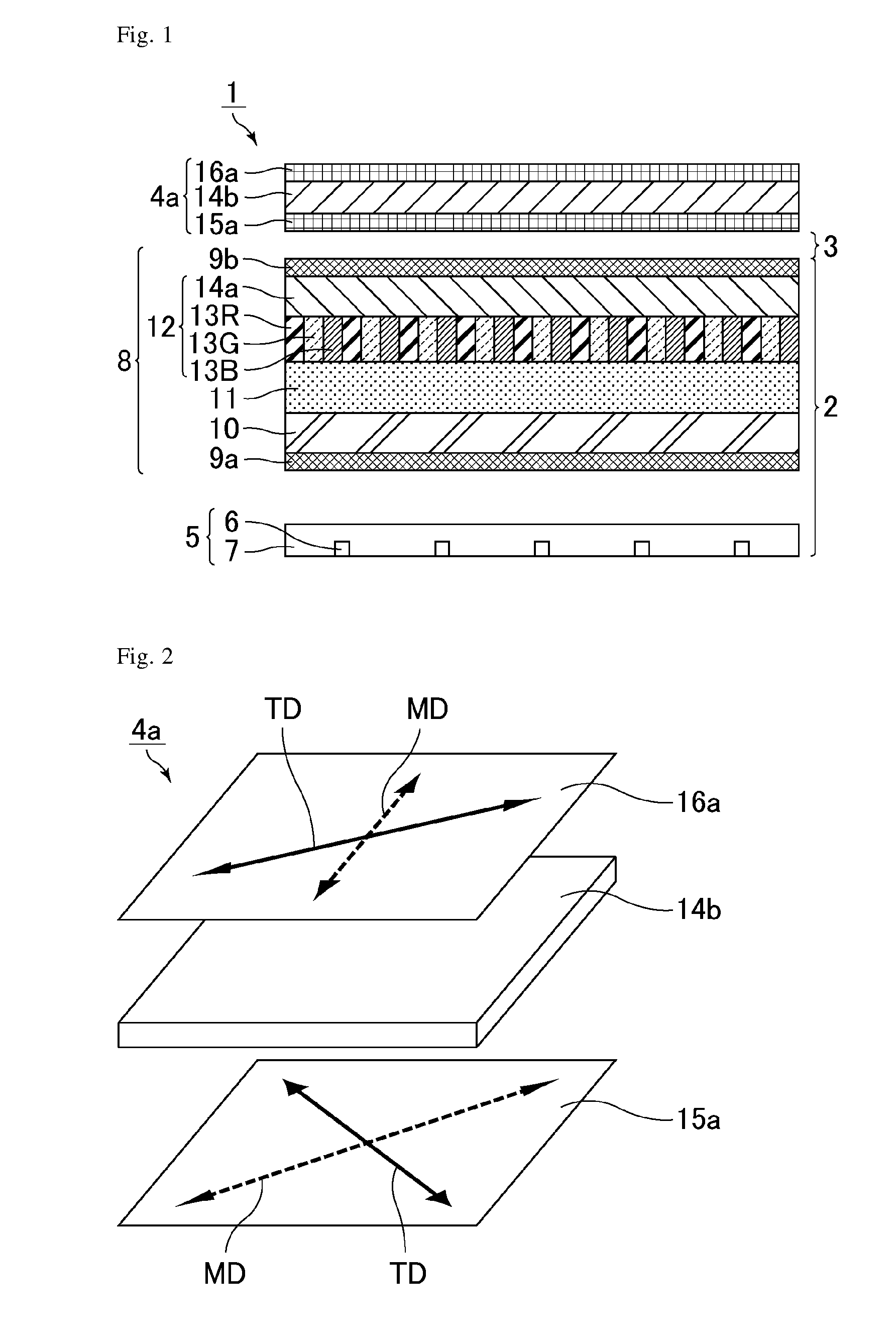
[0041]Example 2 relates to a mirror display that includes a liquid crystal display device, a reflective polarizer as a half mirror layer, and a heat-shrinkable member as a warp-suppressing member. The difference from Example 1 is the arrangement of the MDs (TDs) of the reflective polarizer and the heat-shrinkable member. Since the mirror display of Example 2 is the same as the mirror display of Example 1 except for the above configuration, the explanation of the same respects is omitted here.

[0042]FIG. 3 is a schematic perspective view of a half mirror plate of Example 2. As shown in FIG. 3, a half mirror plate 4b includes, in the order from the back surface side toward the viewing surface side, the reflective polarizer 15a as a half mirror layer, the glass substrate 14b as a base material supporting the half mirror layer, and a heat-shrinkable member 16b as a warp-suppressing member. The respective members were bonded to each other with an adhesive (trade name: PD-S1, not shown, av...

Example

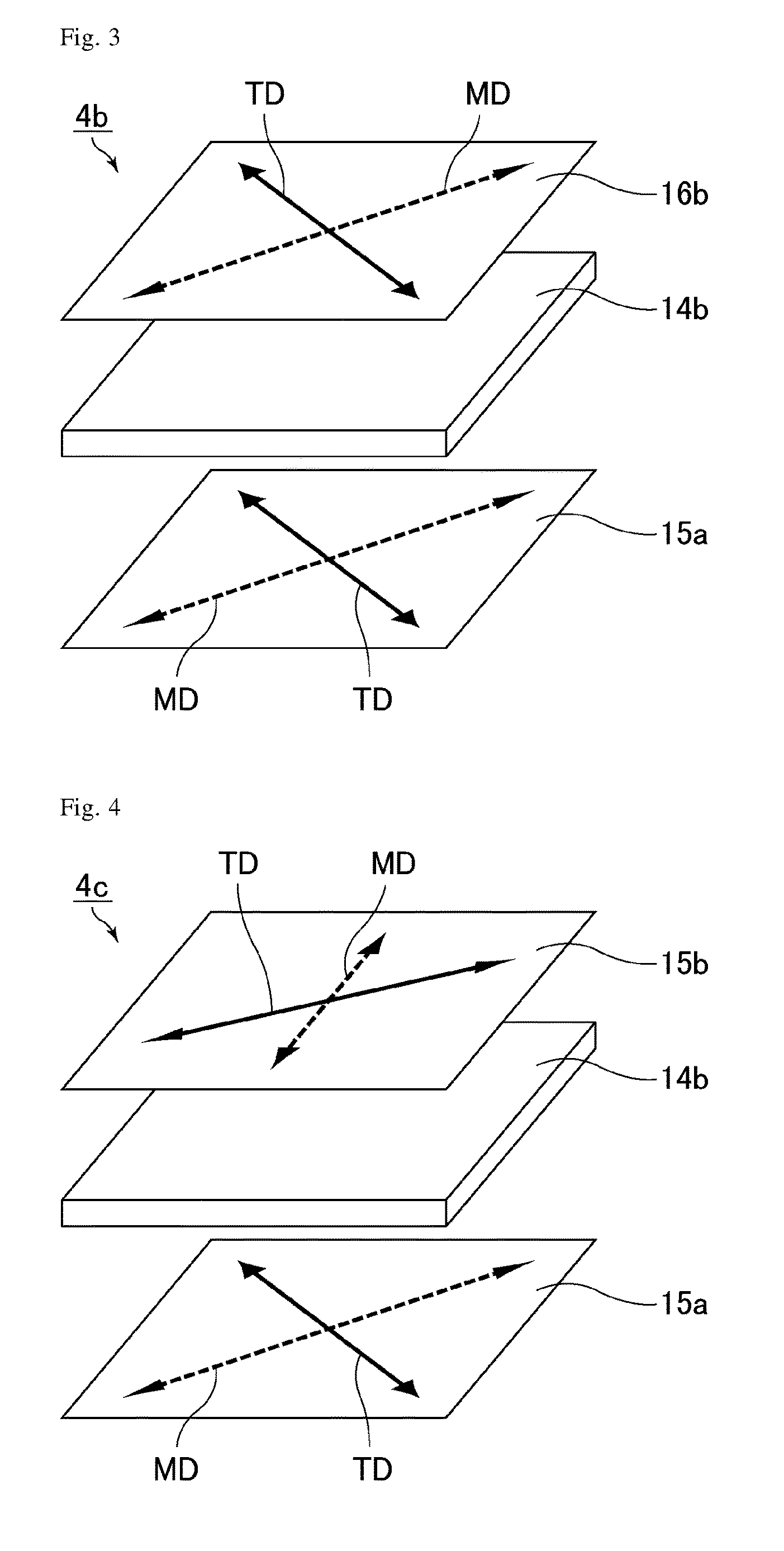
[0048]Example 3 relates to a mirror display that includes a liquid crystal display device, a reflective polarizer as a half mirror layer, and a reflective polarizer as a warp-suppressing member. The difference from Example 1 is use of the reflective polarizer as a warp-suppressing member instead of the heat-shrinkable member. Since the mirror display of Example 3 is the same as the mirror display of Example 1 except for the above configuration, the explanation of the same respects is omitted here.

[0049]FIG. 4 is a schematic perspective view of a half mirror plate of Example 3. As shown in FIG. 4, a half mirror plate 4c includes, in the order from the back surface side toward the viewing surface side, the reflective polarizer 15a as a half mirror layer, the glass substrate 14b as a base material supporting the half mirror layer, and a reflective polarizer 15b (second reflective polarizer) as a warp-suppressing member. The respective members were bonded to each other with an adhesive ...


PUM


Abstract

The present invention provides a mirror display that can suppress warp of a half mirror plate with a reflective polarizer under heat to prevent distortion of a reflected image in a mirror mode. The mirror display of the present invention includes a half mirror plate that includes a first reflective polarizer and a first base material, a display device, and a warp-suppressing member that suppresses shrinking of the first reflective polarizer under heat. The first reflective polarizer and the first base material are integrated, and the display device is disposed on the back surface side of the half mirror plate.

Description

TECHNICAL FIELD[0001]The present invention relates to a mirror display. The present invention specifically relates to a mirror display that provides both a mirror mode serving as a mirror and a display mode providing an image.BACKGROUND ART[0002]Mirror displays, which can serve as a mirror in a non-display state by using a half mirror plate with a half mirror layer provided on the viewing surface side of a display device, have been recently proposed for applications such as digital signage (e.g. Patent Literature 1). A mirror display is usable as a mirror in addition to as a display which is the original purpose. Specifically, when display light is emitted from the display device, the mirror display shows an image owing to the display light in a region where the display light is emitted from the display device. When no display light is emitted from the display device, on the other hand, the mirror display reflects the outside light and serves as a mirror in a region where the displa...

Claims


Application Information

Patent Timeline
IPC IPC(8): G02F1/1335G02B7/00G09F9/35G02B5/30
CPCG02F1/133536G02B5/3041G02B7/008G02F2001/133557G09F9/35G02F2001/133562G02F1/133555G02B5/3033G02F2201/54G02F2203/09G02F1/133562G02F1/133557
Inventor HAKOI, HIROYUKIHASEGAWA, MASAHIROSAKAI, AKIRAMINOURA, KIYOSHI
Owner SHARP KK
Why Eureka
Try Eureka