
Circular polarizing plate and organic electroluminescence panel

Active Publication Date: 2015-06-11
NITTO DENKO CORP
View PDF3 Cites 0 Cited by
  • Summary
  • Abstract
  • Description
  • Claims
  • Application Information

AI Technical Summary

Benefits of technology

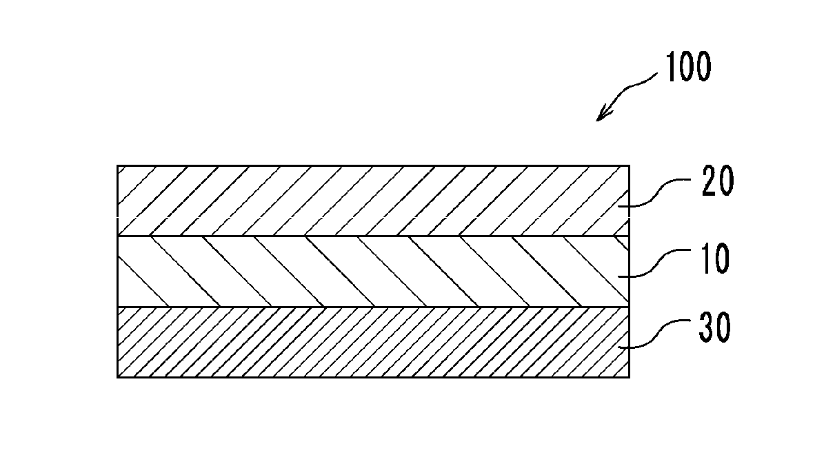
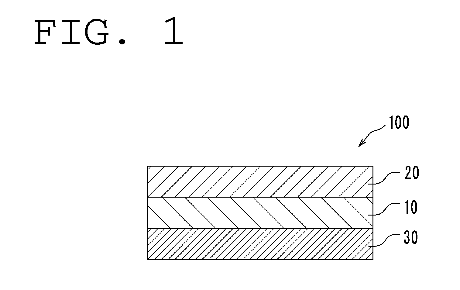
The invention relates to a circularly polarizing plate used in organic EL panels. The technical effect of this patent is to improve the durability of the plate by setting the strength between the polarizer and retardation film to 1.0 N / 20 mm or higher. This allows for direct bonding between the polarizer and retardation film and reduces warping of the panel, resulting in less reflection unevenness on the surface.

Problems solved by technology

The organic EL panel is liable to cause problems such as ambient light reflection and background reflection because the panel includes a metal layer having high reflectivity.
However, a circularly polarizing plate using an ordinary λ / 4 plate involves a serious problem of decoloring.
However, the organic EL panel employing the technology of Patent Literature 2 involves a problem in that the warping of the panel itself occurs, and as a result, reflection unevenness occurs.

Method used


Image

  • Circular polarizing plate and organic electroluminescence panel
  • Circular polarizing plate and organic electroluminescence panel
  • Circular polarizing plate and organic electroluminescence panel

Examples


example 1

Production of Polycarbonate Resin Film

[0130]26.2 Parts by mass of isosorbide (ISB), 100.5 parts by mass of 9,9-[4-(2-hydroxyethoxy)phenyl]fluorene (BHEPF), 10.7 parts by mass of 1,4-cyclohexanedimethanol (1,4-CHDM), 105.1 parts by mass of diphenyl carbonate (DPC), and 0.591 part by mass of cesium carbonate (0.2 mass % aqueous solution) as a catalyst were loaded into a reaction vessel. Under a nitrogen atmosphere, as the first step of a reaction, the heating medium temperature of the reaction vessel was set to 150° C., and the raw materials were dissolved (for about 15 minutes) while being stirred as required.

[0131]Next, a pressure in the reaction vessel was increased from normal pressure to 13.3 kPa, and produced phenol was extracted to the outside of the reaction vessel while the heating medium temperature of the reaction vessel was increased to 190° C. in 1 hour.

[0132]A temperature in the reaction vessel was held at 190° C. for 15 minutes. After that, as a second step, the pressur...

example 2

Production of Polyvinyl Acetal Resin Film

[0138]8.8 Grams of a polyvinyl alcohol-based resin (manufactured by The Nippon Synthetic Chemical Industry Co., Ltd., trade name: “NH-18” (polymerization degree=1,800, saponification degree=99.0%)) were dried at 105° C. for 2 hours, and were then dissolved in 167.2 g of dimethyl sulfoxide (DMSO). 2.98 Grams of 2-methoxy-1-naphthaldehyde and 0.80 g of p-toluenesulfonic acid monohydrate were added to the solution, and the mixture was stirred at 40° C. for 1 hour. 23.64 Grams of 1,1-diethoxyethane (acetal) were further added to the reaction solution, and the mixture was stirred at 40° C. for 4 hours. After that, 2.13 g of triethylamine were added to the mixture to terminate the reaction. The resultant crude product was reprecipitated with 1 L of methanol. A polymer that had been filtered out was dissolved in tetrahydrofuran and reprecipitated with methanol again. The resultant was filtered out and dried to provide 12.7 g of a white polymer. 1H-N...


PUM


Abstract

There is provided a circularly polarizing plate that can prevent light leakage in an organic EL panel and can suppress the warping of the panel to reduce reflection unevenness in a panel surface. A circularly polarizing plate according to an embodiment of the present invention is used in an organic EL panel, and includes a polarizer and a retardation film directly bonded to the polarizer. In-plane retardations of the retardation film satisfy a relationship of Re(450)<Re(550); and a 90° adhesive strength between the polarizer and the retardation film is 1.0 N / 20 mm or more.

Description

TECHNICAL FIELD[0001]The present invention relates to a circularly polarizing plate and an organic EL panel.BACKGROUND ART[0002]In recent years, a display mounted with an organic EL panel has been proposed in association with wide spread use of a thin display. The organic EL panel is liable to cause problems such as ambient light reflection and background reflection because the panel includes a metal layer having high reflectivity. In view of the foregoing, it has been known that those problems are prevented by providing a circularly polarizing plate including a λ / 4 plate on a viewer side. However, a circularly polarizing plate using an ordinary λ / 4 plate involves a serious problem of decoloring. The use of a combination of a λ / 4 plate and a λ / 2 plate (Patent Literature 1), and the use of a λ / 4 plate constituted of the so-called reverse wavelength dispersion material (Patent Literature 2) have each been proposed as means for solving such problem.[0003]Here, when a circularly polariz...

Claims


Application Information

Patent Timeline
IPC IPC(8): G02B5/30G02B1/08
CPCG02B5/305G02B1/08G02B5/3083G02B5/3025H10K59/8791H10K59/50H10K50/86
Inventor IIDA, TOSHIYUKISHIMIZU, TAKASHIMURAKAMI, NAOUWADA, KAZUKIKOJIMA, TADASHI
Owner NITTO DENKO CORP
Learn More