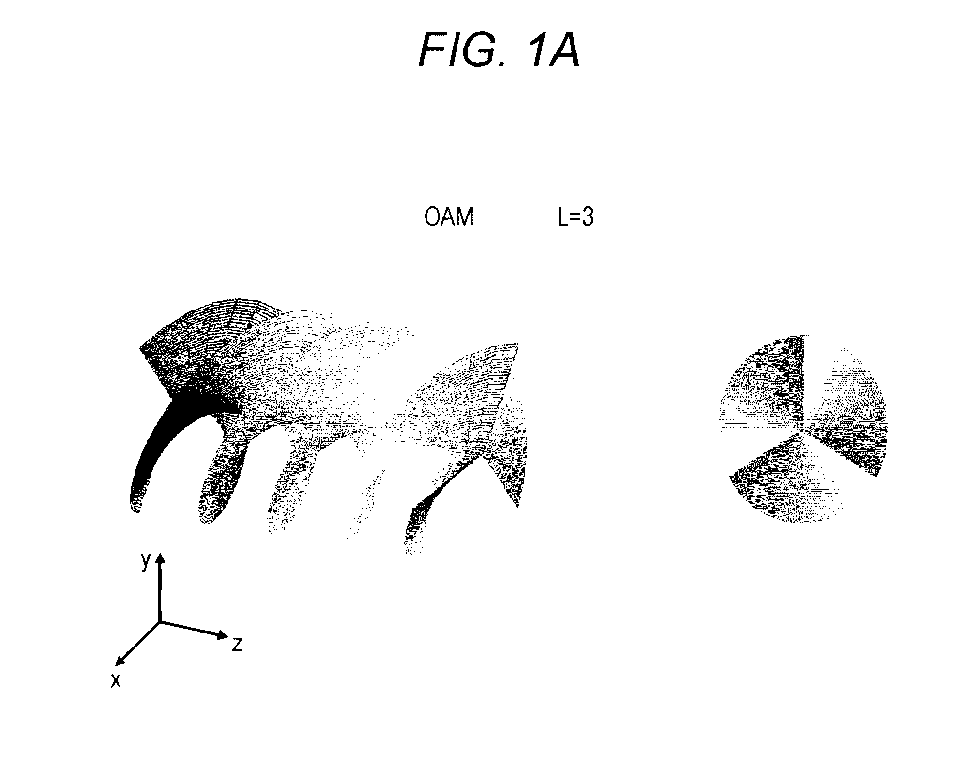
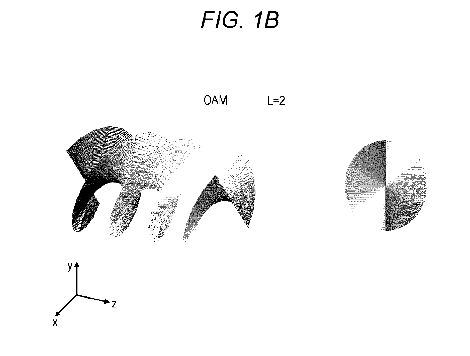
Wireless communication device and wireless communication system
a wireless communication and wireless communication technology, applied in the direction of individual energised antenna arrays, radio transmission, transmission, etc., can solve the problem that the low-gain antenna based on electric field induction cannot be used for high-frequency millimeter waves, and achieve the effect of preventing improper connection and being easy to d
- Summary
- Abstract
- Description
- Claims
- Application Information
AI Technical Summary
Benefits of technology
Problems solved by technology
Method used
Image
Examples
first example
[0102]FIG. 5 illustrates a configuration example (a first example) of a short range wireless communication device 500 using the whirl of waves.
[0103]The short range wireless communication device 500 includes a circular array antenna 501 formed of N antenna elements 501-1, 501-2 to 501-N.
[0104]The antenna elements 501-1, 501-2 to 501-N are each formed of the linearly polarized patch antenna and disposed at regular intervals along a circumference of a circle with a predetermined radius on the top surface of a double-sided printed circuit board with a GND layer formed on the bottom surface thereof (refer to FIG. 2), thereby making up the circular array antenna 501. While a specific configuration of the linearly polarized patch antennas being used will not be described, each antenna has a structure and dimensions to be able to transmit and receive a signal of a desired radio frequency band, namely the millimeter wave band.
[0105]The antenna elements 501-1, 501-2 to 501-N of the short ran...
second example
[0114]FIG. 6 illustrates a configuration example (a second example) of a short range wireless communication device 600 using the whirl of waves.
[0115]The short range wireless communication device 600 includes a circular array antenna 601 formed of N antenna elements 601-1, 601-2 to 601-N.
[0116]The antenna elements 601-1, 601-2 to 601-N are each formed of a linearly polarized patch antenna and disposed at regular intervals along a circumference of a circle with a predetermined radius on a top surface of a double-sided printed circuit board with a GND layer formed on a bottom surface thereof (refer to FIG. 2), thereby making up the circular array antenna 601. While a specific configuration of the linearly polarized patch antenna being used will not be described, each antenna has a structure and dimensions to be able to transmit and receive a signal of a desired radio frequency band, namely the millimeter wave band.
[0117]The short range wireless communication device 600 further include...
third example
[0122]FIG. 7 illustrates a configuration example (a third example) of a short range wireless communication device 700 including antenna units individually for transmission and reception.
[0123]The short range wireless communication device 700 includes a transmission circular array antenna 701 formed of M antenna elements 701-1, 701-2 to 701-M and a reception circular array antenna 711 formed of N antenna elements 711-1, 711-2 to 711-N.
[0124]The antenna elements 701-1, 701-2 to 701-N used for transmission are each formed of a linearly polarized patch antenna and are disposed at regular intervals along a circumference of a circle with a predetermined radius on a top surface of a double-sided printed circuit board with a GND layer formed on a bottom surface thereof (refer to FIG. 2), thereby making up the circular array antenna 701. Moreover, the antenna elements 711-1, 711-2 to 711-N used for reception are each formed of a linearly polarized patch antenna and are disposed at regular in...
PUM
 Abstract
Description
Claims
Application Information
 - R&D
- Intellectual Property
- Life Sciences
- Materials
- Tech Scout
- Unparalleled Data Quality
- Higher Quality Content
- 60% Fewer Hallucinations
Browse by: Latest US Patents, China's latest patents, Technical Efficacy Thesaurus, Application Domain, Technology Topic, Popular Technical Reports.
© 2025 PatSnap. All rights reserved.Legal|Privacy policy|Modern Slavery Act Transparency Statement|Sitemap|About US| Contact US: help@patsnap.com


