Heat conducting module

a heat conducting module and heat conducting technology, applied in the field of heat conducting modules, can solve the problems of reducing the operating efficiency of electronic products, damage to electronic products, and prone to large heat generation of electronic elements inside electronic products, and achieve the effect of increasing the conducting efficiency of the heat conducting module, reducing the thickness of the liquid membrane in the first sub-groove, and increasing the surface tension

Active Publication Date: 2017-03-02
COOLER MASTER CO LTD
View PDF6 Cites 1 Cited by
  • Summary
  • Abstract
  • Description
  • Claims
  • Application Information

AI Technical Summary

Benefits of technology

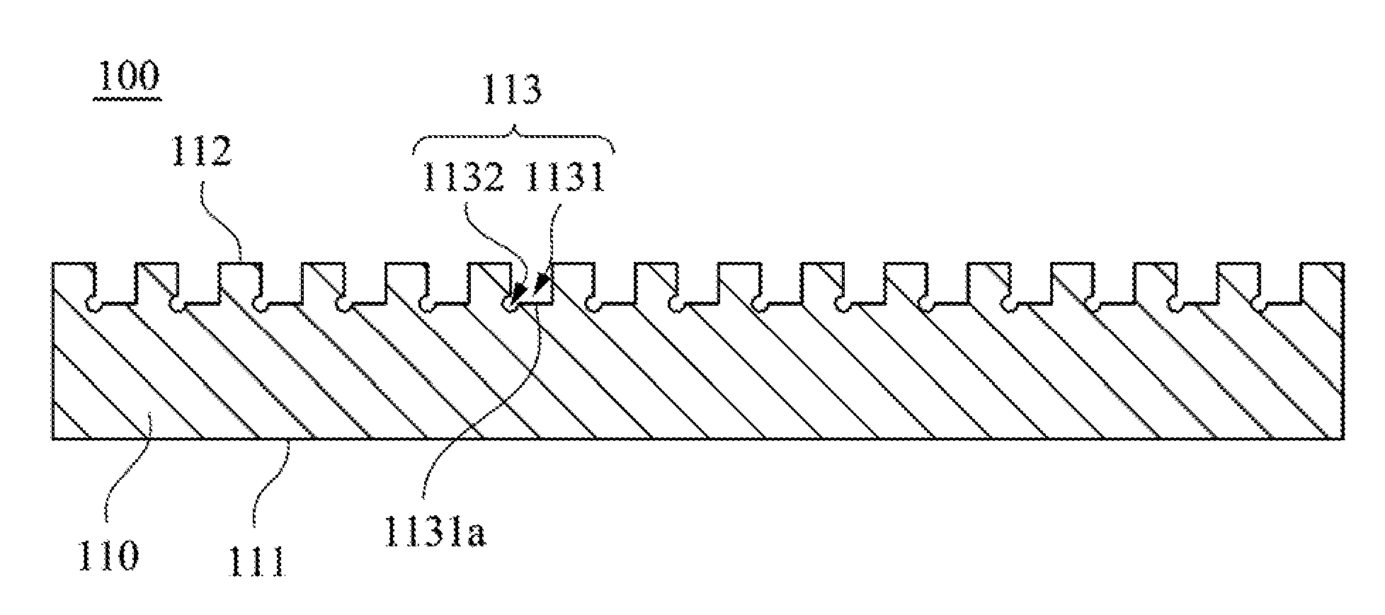
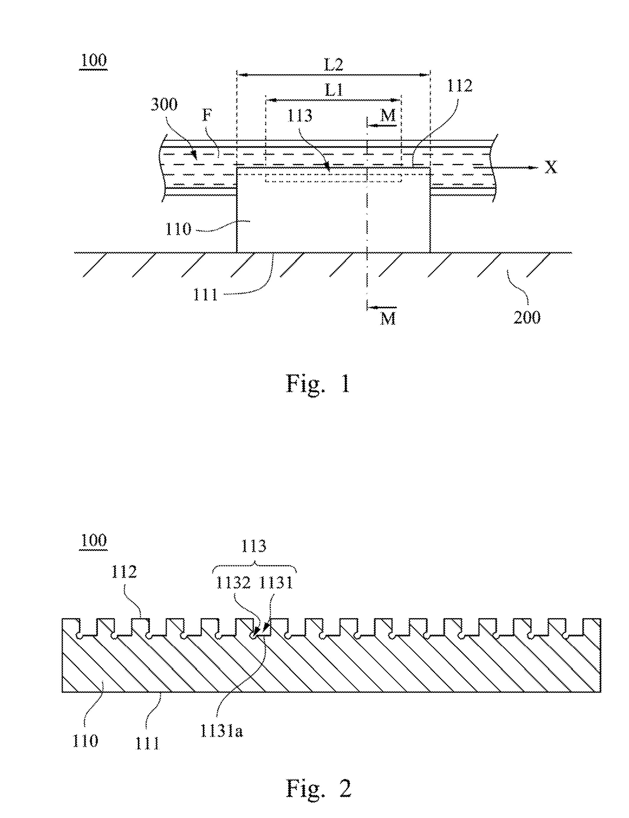
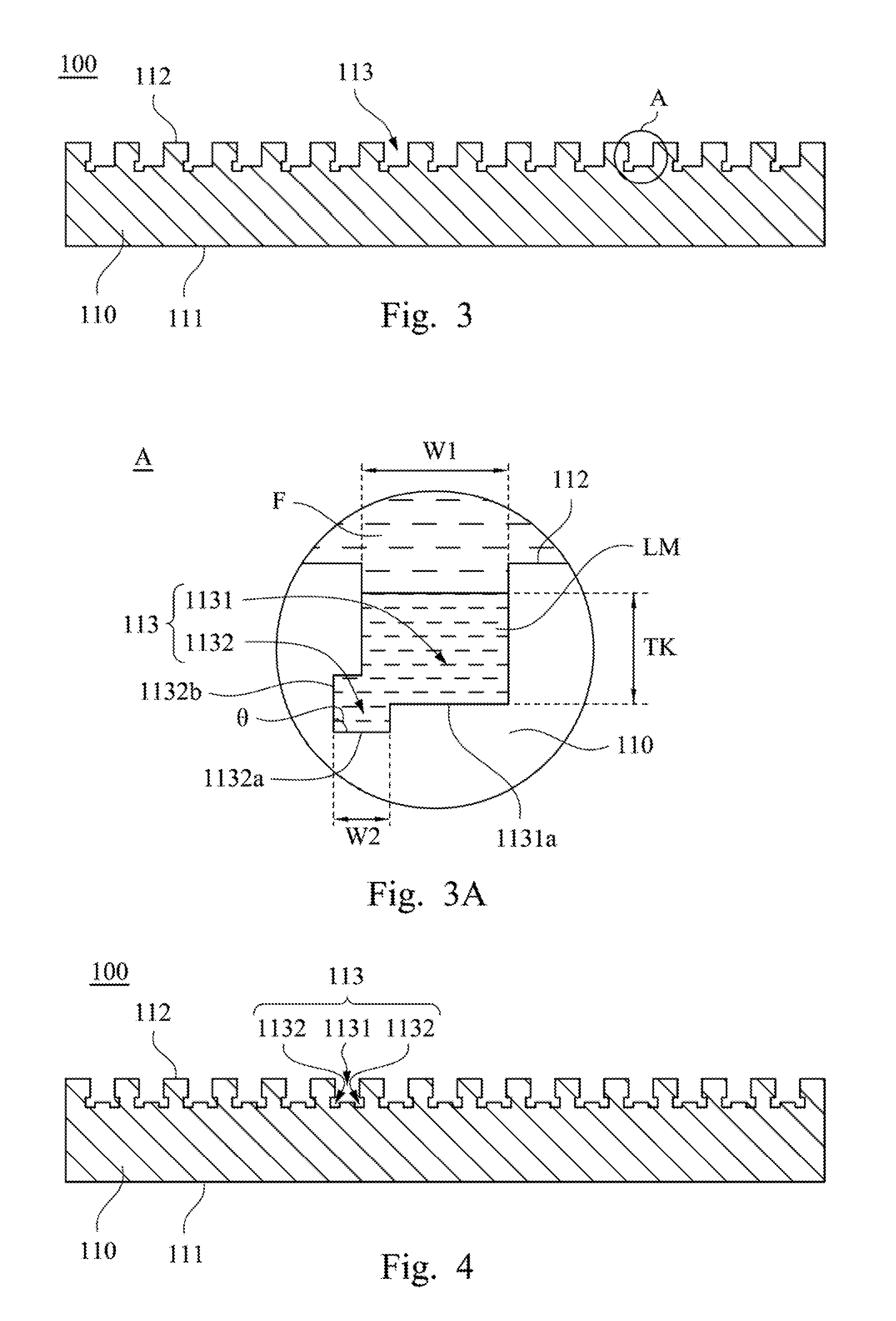
[0017](1) Since the second sub-groove can produce a larger surface tension than the first sub-groove, the liquid membrane in the first sub-groove can be at least partially drawn into the second sub-groove. Consequently, the membrane thickness of the liquid membrane in the first sub-groove can be effectively reduced, and the heat of the other parts of the fluid flowing in the first sub-groove can be more easily conducted to the third surface. As a result the conducting efficiency of the heat conducting module can be correspondingly increased.
[0018](2) Since the side surface and the fourth surface of the second sub-groove form an angle therebetween, the liquid membrane in the first groove is more likely to be drawn into the second sub-groove. This can further facilitate a reduction in the membrane thickness of the liquid membrane in the first sub-groove.

Problems solved by technology

However, during the operation of electronic products with a high efficiency, the electronic elements inside the electronic products are prone to produce a large amount of heat.
Such a large amount of heat can easily cause a reduction in the operating efficiency of the electronic products, and may even lead to damage of the electronic products due to overheating.

Method used


Image

  • Heat conducting module
  • Heat conducting module
  • Heat conducting module

Examples


Embodiment Construction

[0025]Drawings will be used below to disclose embodiments of the present disclosure. For the sake of clear illustration, many practical details will be explained together in the description below. However, it is appreciated that the practical details should not be used to limit the claimed scope. In other words, in some embodiments of the present disclosure, the practical details are not essential. Moreover, for the sake of drawing simplification, some customary structures and elements in the drawings will be schematically shown in a simplified way. Wherever possible, the same reference numbers are used in the drawings and the description to refer to the same or like parts.

[0026]Unless otherwise defined, all terms (including technical and scientific terms) used herein have the same meaning as commonly understood by one of ordinary skill in the art to which this disclosure belongs. It will be further understood that terms, such as those defined in commonly used dictionaries, should b...


PUM


Abstract

A heat conducting module includes a main body. The main body includes a first surface and a second surface. The first surface is thermally connected to a heat absorbing body. The second surface is opposite to the first surface and is fluidly connected to a channel. The second surface has a plurality of grooves disposed along a direction. The channel allows a fluid to flow a long the direction. Each of the grooves includes a first sub-groove and at least one second sub-groove. The first sub-groove at least has a third surface close to the first surface. The first sub-groove at least partially communicates with the second sub-groove, and the second sub-groove is at least partially fluidly connected with the third surface.

Description

RELATED APPLICATIONS[0001]This application claims priority to Taiwanese Application Serial Number 104128468, filed Aug. 28, 2015, which is herein incorporated by reference,BACKGROUND[0002]Technical Field[0003]The present disclosure relates to a heat conducting module. More particularly, the present disclosure relates to a heat conducting module with sub-grooves.[0004]Description of Related Art[0005]With advancements in technology, the market has been flooded with a variety of electronic products. Moreover, in order to satisfy consumer demand related to increasingly higher requirements, in addition to becoming smaller in size, many electronic products are becoming more and more efficient.[0006]However, during the operation of electronic products with a high efficiency, the electronic elements inside the electronic products are prone to produce a large amount of heat. Such a large amount of heat can easily cause a reduction in the operating efficiency of the electronic products, and m...

Claims


Application Information

Patent Timeline
Patent Type & Authority Applications(United States)
IPC IPC(8): H05K7/20
CPCH05K7/20409H05K7/20218H05K7/20254F28F2260/02F28F13/187H01L23/473
Inventor WANG, CHI-CHUANLIN, KUO-WEI
Owner COOLER MASTER CO LTD
Why Eureka
Try Eureka