
System for mounting, accessing, moving and folding away articles on, under or along a surface

a technology for moving and folding articles, applied in the field of articles and systems of articles, can solve the problems of inherently weak or unstable mountings, inability to easily move once installed, and inability to easily remove articles for servicing, etc., and achieve the effects of maximizing adjustability, reliability, and maximizing the use of available spa

Active Publication Date: 2017-03-09
BEANIUS
View PDF3 Cites 6 Cited by
  • Summary
  • Abstract
  • Description
  • Claims
  • Application Information

AI Technical Summary

Benefits of technology

The present invention is a system that allows for the mounting, accessing, moving, and folding away of articles such as appliances and organizing / storage vessels on, under, or along surfaces in various environments. The system is easy to install, requires minimal tools and planning, and can be securely attached to surfaces using adhesive tape or screws. It also allows for the folding away of articles when not in use, without interfering with work areas underneath them. The system includes a clamshell-shaped configuration that can hold a wide range of flat payloads of varying widths and depths, and a height-adjustable payload carrier that can be easily attached to surfaces and folded away when not in use. The system also allows for the easy mounting, accessing, moving, and folding away of articles on any surface, including countertops. Overall, the system provides a flexible and adjustable solution for mounting and accessing articles in various environments.

Problems solved by technology

They cannot be moved easily once installed.
It follows that these articles also cannot easily be removed for servicing, adjustment and / or cleaning.
Many have inherently weak or unstable mountings due to the small footing areas they span or due to their dependence on only a comparatively thin bottom panel of the cabinet for stability.
In use (when deployed / pulled-down) many of these prior art are inconveniently oriented with respect to the user and their intended use and lack the adjustability to remedy the situation.
In only a few cases do the articles have some limited means to adjust their position for easier use and / or access by the user.
Items wider than these units themselves cannot be folded up into the units (e.g., a wide book in a narrow bookholder) since such wide items would interfere with the folding mechanisms and / or support framing.
None provide a means for easily (i.e., by hand, without tools) moving and remounting the article along the length of the downwardly facing surface (e.g., a cabinet bottom) and it follows that none of these articles can be moved in this way while in use.
Due to their differences in design approach and a lack of common parts, very little manufacturing, development, user training and marketing efficiencies (cost savings) can be realized among these inventions.
These inventions have many significant limitations including their instability, lack of a pull-down / fold-up capability, difficult and inflexible installation, significant limitations on lateral positioning of items and their cumbersome and inflexible means of mounting, moving, and removing articles.
These systems also do not employ any common / standard means of power delivery where electric power is required for a specific article (e.g., flat panel video screen).
Each track must be attached via a single line of screws / fasteners to a cabinet bottom thus the strength of the cabinet bottom and the straight-line configuration of the screws limit the strength and (torquing) stability of the system.
Since the attachment of articles to the track depends on engagement with cutout slots in the track, the track does not lend itself to being made available in a nested, telescoping format.
As it cannot expand lengthwise to fit the mounting surface, the track would have to be cut to size to fit under the cabinet.
If provided in standard lengths, it is likely these standard lengths would not fully utilize the potential mounting space under the cabinet in most cases.
This not only requires a good deal of effort but also in many cases requires that the article be at least partially dismantled and taken out of use to be removed or moved.
Height, tilt, protrusion are not adjustable by any means in this system.
There is also no facility for folding the appliance up out of the way when not in use, no standard means of power delivery, and no way for users to adjust the appliances height, tilt and protrusion relative to the cabinet and themselves.
Again, there is also no facility for folding the appliance up out of the way when not in use, no standard means of power delivery, and adjusting the appliances for height, tilt and protrusion relative to the cabinet requires tools.
The system did not however address storage and access on vertical surfaces and countertops.
Also its rail arrangement dictated that the undercabinet articles fall essentially within the standard width of its rails and carriage, and that any additional space provided by the cabinet depth could not be utilized outside of this footprint.
The rail arrangement depicted (two facing concaved elongated members) also dictated use of a retractable footing arrangement that was not mechanically optimal with respect to manufacturing cost and reliability of engagement.
There was also no specific space or method provided for integrating undercabinet lighting with the system.
However, none of the references taken in any combination suggest transforming a rail-based storage support so that it rests on the counter and then coupling a payload to the storage support where the tram was previously connected or vice versa.

Method used


Image

  • System for mounting, accessing, moving and folding away articles on, under or along a surface
  • System for mounting, accessing, moving and folding away articles on, under or along a surface
  • System for mounting, accessing, moving and folding away articles on, under or along a surface

Examples


Embodiment Construction

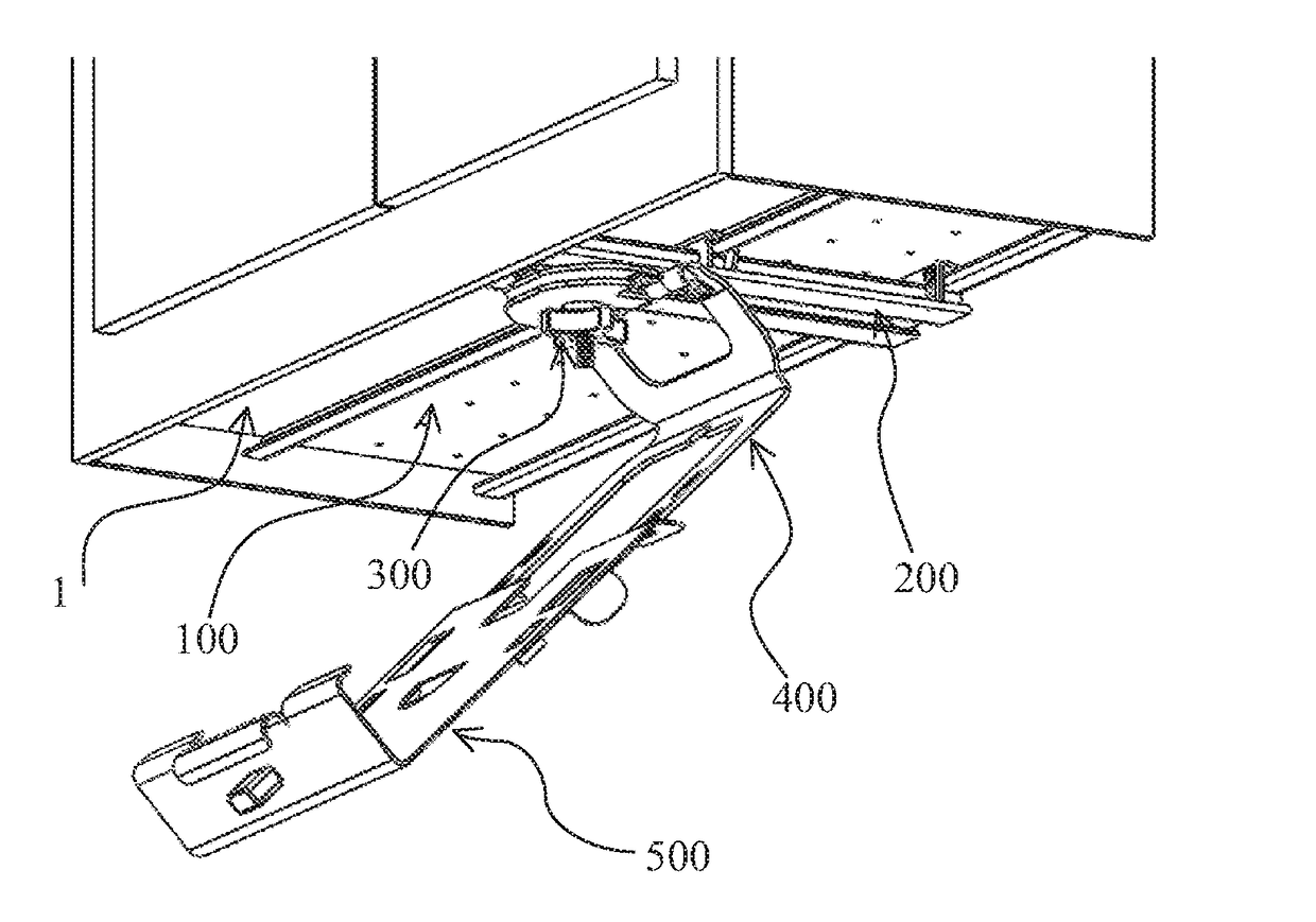
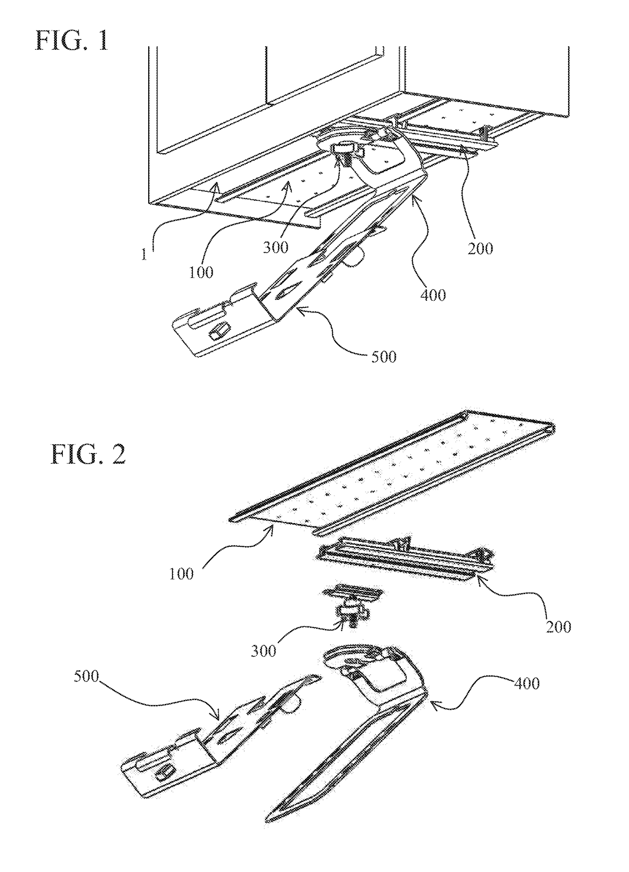
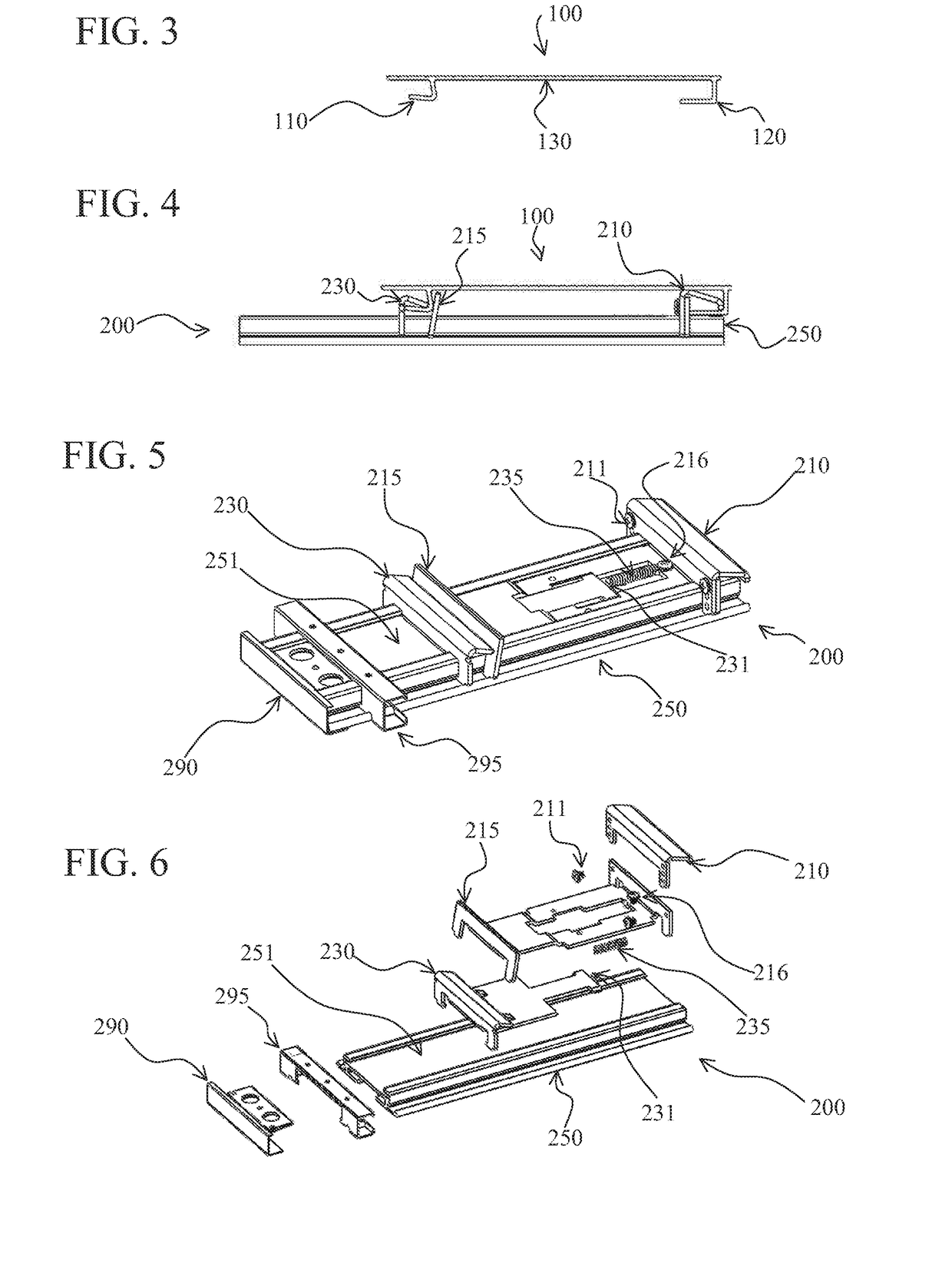
[0079]FIG. 1 is an overview drawing of the preferred embodiment showing the five key component elements of the system (100, 200, 300, 400, 500) in one of the many possible deployment configurations of the system. FIG. 2 shows an exploded view of those same five key components elements of the system. In the deployment configuration of FIG. 1 the payload carrier 500 (in this case a book easel) is positioned forward and diagonally protruding from underneath a high kitchen cabinet bottom 1. The tram-rail unit 100 is fixed to the downwardly facing surface of the cabinet 1 by attachment means that can include screws, other fasteners and / or adhesives. The lock-on carriage assembly 200 is slidably engaged onto and suspended from the tram-rail unit 100 allowing the lock-on carriage 200 to be moved anywhere along the length of the tram-rail 100 without disengaging the lock-on carriage 200. The moveable anchor-post 300 slides front-to-back in the lock-on carriage assembly 200. The multi-surfac...


PUM


Abstract

It is the objective of the present invention to create additional functional, flexible and accessible work and storage area in the home, office, workshop, automobile, medical and industrial environments by providing means to firmly and securely mount, store and access articles such as appliances (e.g., flat panel video displays / monitors, can openers, weighing scales) and organizing / storage vessels (e.g., spice racks, first aid kits, sewing boxes, knife blocks, tool kits) on downwardly facing surfaces, such as the underside of cabinets and shelves, and on vertical surfaces (such as cabinet doors and frames) and by enhancing access to those articles on horizontal surfaces such as countertops. The invention performs its functions using a small number of readily manufacturable, modular, standardized components. The invention also performs its functions maximizing adjustability, reliability, use of available space and ease and flexibility of installation.

Description

FIELD OF THE INVENTION[0001]This invention relates to articles and systems of articles, primarily appliances and storage / organizing devices, that are designed to mount under downwardly facing, vertical or horizontal surfaces such as, but not limited to, cabinets, shelves and countertops, in work areas such as those found in kitchens, workshops, offices, hospitals, utility rooms, storage rooms, laundry rooms or industrial / fabrication facilities.PRIOR ART[0002]Functional, flexible, accessible work and storage area is needed in virtually all home, office, shop and industrial environments. The size of this usable work and storage area can be substantially augmented by firmly and securely mounting articles such as appliances (e.g., can openers, bookholders, flat panel video displays) and organizing / storage vessels (e.g., spice racks, first aid kits, knife drawers, tool boxes) onto downwardly facing surfaces, such as underneath cabinets or shelves. Any system or arrangement addressing und...

Claims


Application Information

Patent Timeline
IPC IPC(8): A47B23/04F16M13/02F16M11/42F16M11/10F16M11/20
CPCA47B23/043F16M11/10F16M11/2014F16M11/2085F16M2200/027F16M11/425F16M13/027F16M2200/022F16M11/2092F16M13/022
Inventor BEHROOZI, RYAN H.
Owner BEANIUS
Learn More