Sheet feeding apparatus and image forming apparatus

a technology of feeding apparatus and image forming apparatus, which is applied in the direction of electrographic process apparatus, thin material handling, instruments, etc., can solve the problem of hard vibration noise produced

Active Publication Date: 2017-03-09
CANON KK
View PDF5 Cites 5 Cited by
  • Summary
  • Abstract
  • Description
  • Claims
  • Application Information

AI Technical Summary

Benefits of technology

[0009]A sheet feeding apparatus according to one aspect of this disclosure includes a feed roller configured to feed a sheet in a feeding direction, a drive unit configured to drive the feed roller, a separation roller connected to the drive unit through a torque limiter, a conveyance portion configured to convey the sheet with a conveyance nip portion at which the sheet is nipped, and a control portion configured to execute a first control mode in which a first sheet is conveyed and a second control mode in which a second sheet having a lower basis weight than that of the first sheet is conveyed. The conveyance nip portion is disposed downstream of the separation nip portion in the feeding direction. The separation roller is configured to be driven in a direction against the feeding direction so that sheets are separated at a separation nip portion formed between the feed roller and the separation roller. The control portion starts the drive unit, and stops the drive unit with the sheet nipped at both nips of the separation nip portion and the conveyance nip portion in each of the first and second control modes. The control portion sets a stop timing of the drive unit in the first control mode to a timing later than that in the second control mode.

Problems solved by technology

However, in a case of employing such a configuration, the separation roller repeatedly rotates normally and reversely little by little and vibrates in some cases when the sheet is fed.
In the case where the separation roller continues vibrating with high amplitude, there is a concern that harsh vibration noise will be produced.

Method used


Image

  • Sheet feeding apparatus and image forming apparatus
  • Sheet feeding apparatus and image forming apparatus
  • Sheet feeding apparatus and image forming apparatus

Examples


first embodiment

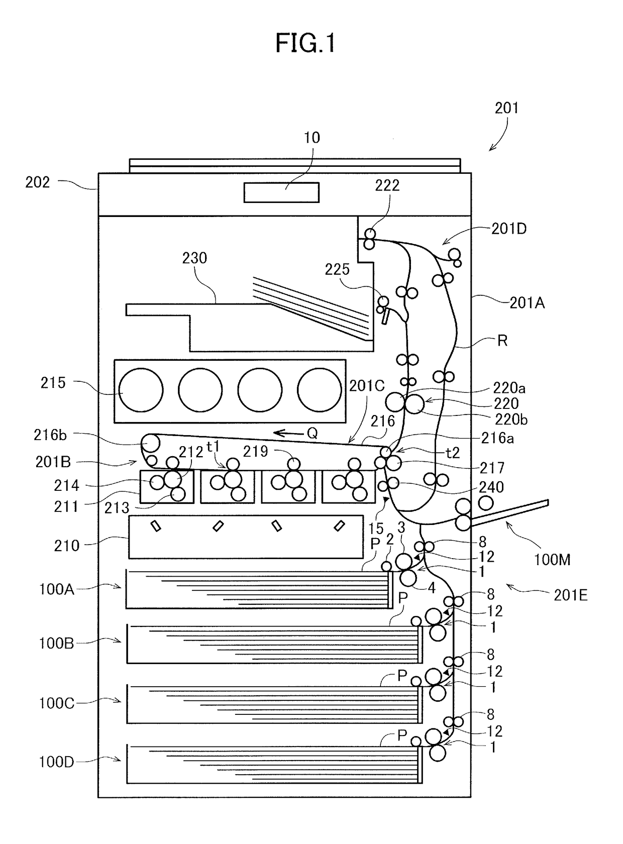
[0029]An image forming apparatus 201 according to the first embodiment is an image forming apparatus such as a full-color laser printer, a general arrangement of which is illustrated in FIG. 1. The image forming apparatus 201 includes an image forming unit 201B forming an image on a sheet P and a fixing portion 220 fixing an image on the sheet P, in an apparatus body 201A, i.e., a printer body or an image forming apparatus body. An image reading apparatus 202 reading an image data of a document is arranged above the apparatus body 201A in a posture in which a supporting surface of the document is positioned approximately horizontally. A sheet discharge tray 230 is provided in a discharge space to which the sheet P is discharged between the image reading apparatus 202 and the apparatus body 201A. Further, a sheet feeding unit 201E feeding sheets P to the image forming unit 201B is provided in the apparatus body 201A. The sheet feeding unit 201E includes sheet feeding apparatuses 100A...

second embodiment

[0085]Next, a sheet feeding operation of the sheet feeding apparatus 100A according to the second embodiment will be described. The sheet feeding apparatus 100A according to the present embodiment differs from that according to the first embodiment described above in that the feeding speed and the image forming speed is fixed, and has the same configuration as that according to the first embodiment except for that difference. Therefore, the same reference signs are assigned to the elements having the same configuration and effects, and description thereof is omitted.

[0086]Similar to the first embodiment, the control portion 9 according to the embodiment performs a process of selecting a control mode according to the type of sheet P inputted by a user. In other words, as shown in FIG. 11, when a user operates the operation panel 10 and selects and inputs types (material and basis weight) of sheet P (S3) with the size of the sheet P being detected through the size detection sensor (S1...

third embodiment

[0089]Next, a sheet feeding operation of the sheet feeding apparatus 100A according to the third embodiment will be described. The sheet feeding apparatus 100A according to the present embodiment differs from that according to the first embodiment described above in that a stop timing of the feeding motor M1 is determined based on a detection signal from the feeding sensor 12. The sheet feeding apparatus has the same configuration as that according to the first embodiment except for that difference, thus the same reference signs are assigned to the elements having the same configuration and effects, and description thereof is omitted.

Case of Long Sheet

[0090]In addition, a sheet feeding operation performed when the sheet P having relatively long sheet length L1 is conveyed will be described with reference to FIG. 12. Here, FIG. 12 is a diagram in which a time chart of drive controls of the feeding motor M1 and the drawing motor M2 is combined with a line diagram indicating a change i...


PUM


Abstract

A sheet feeding apparatus includes a feed roller, a separation roller configured to form a separation nip portion with the feed roller, and a drive unit configured to drive the feed roller and the separation roller. A control portion to control the drive unit stops the drive unit with a sheet nipped at both the separation nip portion and a conveyance nip portion provided in a conveyance portion disposed downstream of the separation nip portion. In the case where a second sheet having lower basis weight than that of a first sheet is conveyed, the control portion set a stop timing of the drive unit to a timing later than that in the case where the first sheet is conveyed.

Description

BACKGROUND OF THE INVENTION[0001]Field of the Invention[0002]This disclosure relates to a sheet feeding apparatus configured to separate and feed sheets and an image forming apparatus including the sheet feeding apparatus.[0003]Description of the Related Art[0004]In many cases, a sheet feeding apparatus provided in an image forming apparatus is configured to separate sheets stacked on a stacking member such as a cassette one by one with a feed roller and the like, and to feed the sheets to a conveyance portion disposed downstream of the feed roller.[0005]Japanese Patent Laid-Open No. 2001-348129 discloses a paper feeder that includes a feed roller configured to feed a paper stacked on a feed tray, a registration roller conveying the sheet to a downstream side of the feed roller, and a control portion to which a sheet size is inputted through an operation panel. The paper feeder causes the feed roller to start rotating, and then, causes the feed roller to stop being driven at a timin...

Claims


Application Information

Patent Timeline
Patent Type & Authority Applications(United States)
IPC IPC(8): G03G15/00B65H3/06B65H5/06B65H7/02
CPCG03G15/6529B65H5/062B65H3/0669B65H7/02G03G15/6511G03G2215/00742
Inventor FUJITA, KEIKO
Owner CANON KK
Why Eureka
Try Eureka