Nonwoven Web With Enhanced Barrier Properties

a technology of enhanced barrier and nonwoven web, which is applied in the direction of protective garments, other domestic objects, bands, etc., can solve the problems of increased barrier capacity of layers and more easily occurring undesirable seepage through barriers, and achieve the effect of increasing the barrier capacity of layers

Inactive Publication Date: 2018-06-28
PFNONWOVENS CZECH SRO
View PDF6 Cites 7 Cited by
  • Summary
  • Abstract
  • Description
  • Claims
  • Application Information

AI Technical Summary

Benefits of technology

[0027]The term “nonwoven textile” means a structure in the form of a fleece or fibrous layer formed from directed or randomly oriented fibres, from which initially a batt is formed and which is subsequently mutually interconnected (consolidated). Fibres are mutually bonded by friction, effects of cohesive forces, gluing with bonds or other adhesives or thermoplastically creating a single or multiple cohesive—bonding patterns consisting of bonding imprints formed by a bonding compression and/or the effect of pressure, heat, ultrasound or heat energy or a combination of these effects if necessary. The term does not refer to fabrics formed by weaving or knitting or fabrics using yarn or fibres to form bonding stitches. The fibres may be of natural or synthetic origin and may be staple fibres, continuous fibres or fibres produced directly at the processing location. Standard available fibres have a diameter ranging from approx. 0.0001 mm up to approx. 0.25 mm and are supplied in several different forms: short fibres (also known as staple fibres). Continuous single fibres (so-called filaments or mono-filaments) or bundles of continuous fibres (so-called multi-filaments or cables) and bundles of continuous fibres with a common twist (yarn). A nonwoven textile can be produced using many methods, including technologies such as meltblown, spunbond, spunmelt, spinning from solvents, electrostatic s

Problems solved by technology

Thus by this reasoning: the smaller and the more curved the pores, the more complicated will be the seepage of, for example, fluids and this will increase the barrier

Method used


Image

  • Nonwoven Web With Enhanced  Barrier Properties
  • Nonwoven Web With Enhanced  Barrier Properties
  • Nonwoven Web With Enhanced  Barrier Properties

Examples


example 1

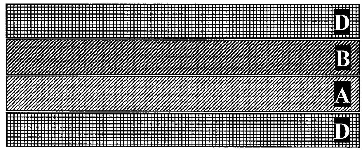
DBD (Comparative Example)

[0102]Both used meltblown beams are of the Reicofil type and together they create a homogeneous layer of fibres, which in principle correspond to fibres forming layer B in examples 3+4 according to the invention. See FIG. 4-a.

example 2

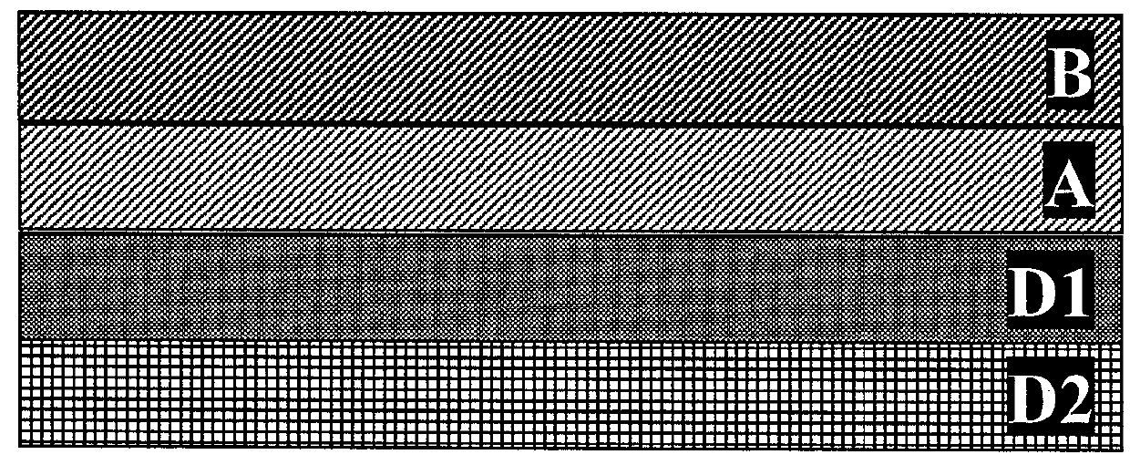
DAD (Comparative Example)

[0103]Fibre layer A is formed by a meltblown beam using advanced meltblown technology Nanospun MB from REICOFIL—Dietip No.117 fitted on a pilot line from REICOFIL and forms a layer of fibres, which in principle corresponds to the fibres forming layer A in examples 3+4 based on the invention. See FIG. 4-b.

example 3

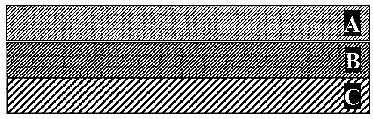
DABD (Example According to the Invention)

[0104]One of the used beams is a Reicofil type meltblown beam and creates layer B.

[0105]The second beam is an advanced meltblown technology Nanospun MB from REICOFIL—Dietip No. 117 that is installed on a REICOFIL pilot line, and forms layer A. See FIG. 4-c.

[0106]The ratio of the basis weight of layer A and layer B is 1:1.


PUM

PropertyMeasurementUnit
Fractionaaaaaaaaaa
Fractionaaaaaaaaaa
Fractionaaaaaaaaaa

Abstract

This invention relates to nonwoven textile with barrier properties containing a first barrier layer A with a theoretical cover coefficient TCC A, and consisting of fibres having a median fibre diameter in the layer of dAm, and a second barrier layer B with a theoretical cover coefficient TCC B, and consisting of fibres having a median fibre diameter in the layer of dBm; while the first barrier layer A and the second barrier layer B are together in direct contact. The median diameters of fibres in the first and second layer have a theoretical fibre diameter coefficient x=(dBm−dAm)/dAm, where the theoretical fibre diameter coefficient x is less than or equal to 1 and where the theoretical fibre diameter coefficient x is greater than or equal to 0.25, and the sum of the theoretical cover coefficient TCC A and TCC B is greater than or equal to 50%.

Description

FIELD OF THE INVENTION[0001]The invention relates to a bulky spunmelt-type nonwoven textile containing several mutually supportive layers with various fibre diameters. The nonwoven textile of this type is intended predominantly for use in the hygiene industry but can be used wherever barrier properties are required—for example, as a material for protective garments in medicine, industry or for use in healthcare.BACKGROUND ART[0002]A nonwoven textile may be utilised in a wide range of applications. Various nonwoven textiles may contain spunbond, meltblown, spunbond (“SMS”) layers, where the contained outer textile layers are formed by a thermoplastic spunbond (e.g. from polyolefins) and the inner layers by a thermoplastic meltblown material. The SMS nonwoven textile of this type may contain stable spunbond layers and an inner meltblown layer, which despite being porous has the ability to prevent, for example, rapid seepage of fluids such as for example bodily fluids or solid compound...

Claims


Application Information

Patent Timeline
IPC IPC(8): B32B5/02A61F13/514A61F13/494A61F13/15A41D13/00B32B5/26B32B7/02D04H3/016D04H3/14
CPCB32B5/022A61F13/51401A61F13/49413A61F13/15203A41D13/00B32B5/26B32B7/02D04H3/016D04H3/14A61F2013/15406A61F2013/51033A61F2013/51452A61F2013/51028A61F2013/4948B32B2307/7242B32B2307/7265B32B2555/02B32B2571/00B32B2437/00A61F13/514B32B5/145D04H3/007D04H3/16B32B2307/7246
Inventor MECL, ZDENEKKOHUT, JAROSLAVKASPARKOVA, PAVLINA
Owner PFNONWOVENS CZECH SRO
Why Eureka
Try Eureka