
X-ray fluoroscopic imaging system

a fluoroscopic imaging and fluorescence technology, applied in the field of x-ray fluorescence imaging system, can solve the problems of limited penetration energy, low ray energy, limited volume of subject that can be checked, etc., and achieve the effects of low cost, simple structure and fast speed

Active Publication Date: 2015-07-02
NUCTECH CO LTD +1
View PDF9 Cites 7 Cited by
  • Summary
  • Abstract
  • Description
  • Claims
  • Application Information

AI Technical Summary

Benefits of technology

The present invention is a fluoroscopic imaging system that can inspect multiple subjects simultaneously using a single electron accelerator, X-ray beams, and detectors. This design has several advantages including fast inspection speed, simple structure, low cost, higher security reliability, and the ability to extract more X-ray beams for a wider view angle or material recognition. The X-ray beams have a fan-shaped region with small energy spread, uniform intensity distribution, small target point, and can be extracted at a large angle, leading to improved image quality. The X-ray fluoroscopic imaging system can be designed in different forms and has the advantages of simple structure, low cost, strong function, and good image quality.

Problems solved by technology

With respect to the inspection system for large-sized cargoes using Cobalt-60, on one hand, the energy of rays is low, the penetration energy is limited, and the volume of the subject that can be checked is limited; on the other hand, Cobalt-60 has a inherent half-time period of 5.27 years, and thus the ray source has to be replaced after a period of time, otherwise the image quality will degrade due to the weakening of ray intensity.
The inspection system for large-sized cargoes using Cobalt-60 has many problems in safety management due to the inherent radioactivity of Cobalt-60, unlike the electron accelerator system, in which X-ray is generated only when power is on and the beam is produced, and which is safe when the beam is stopped or power is off.
Generally only one X-ray beam is extracted for the system with only one inspection channel, and thus the inspection speed is slow and the efficiency is low.
The Cobalt-60 γ-ray source has its particularity in using and processing, such as a shutter device and the like, and has shortages such as low energy, limited penetration capability; short inherent decay, short life, which requires periodic replacement; long-term radiation, large difficulty in safety management, etc.

Method used


Image

  • X-ray fluoroscopic imaging system
  • X-ray fluoroscopic imaging system
  • X-ray fluoroscopic imaging system

Examples


Embodiment Construction

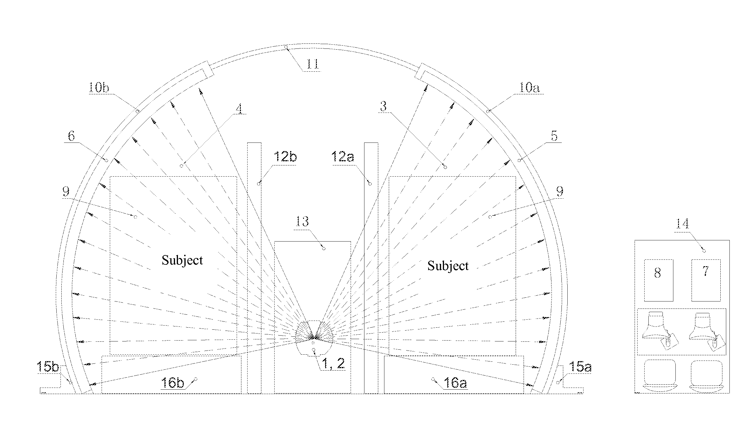
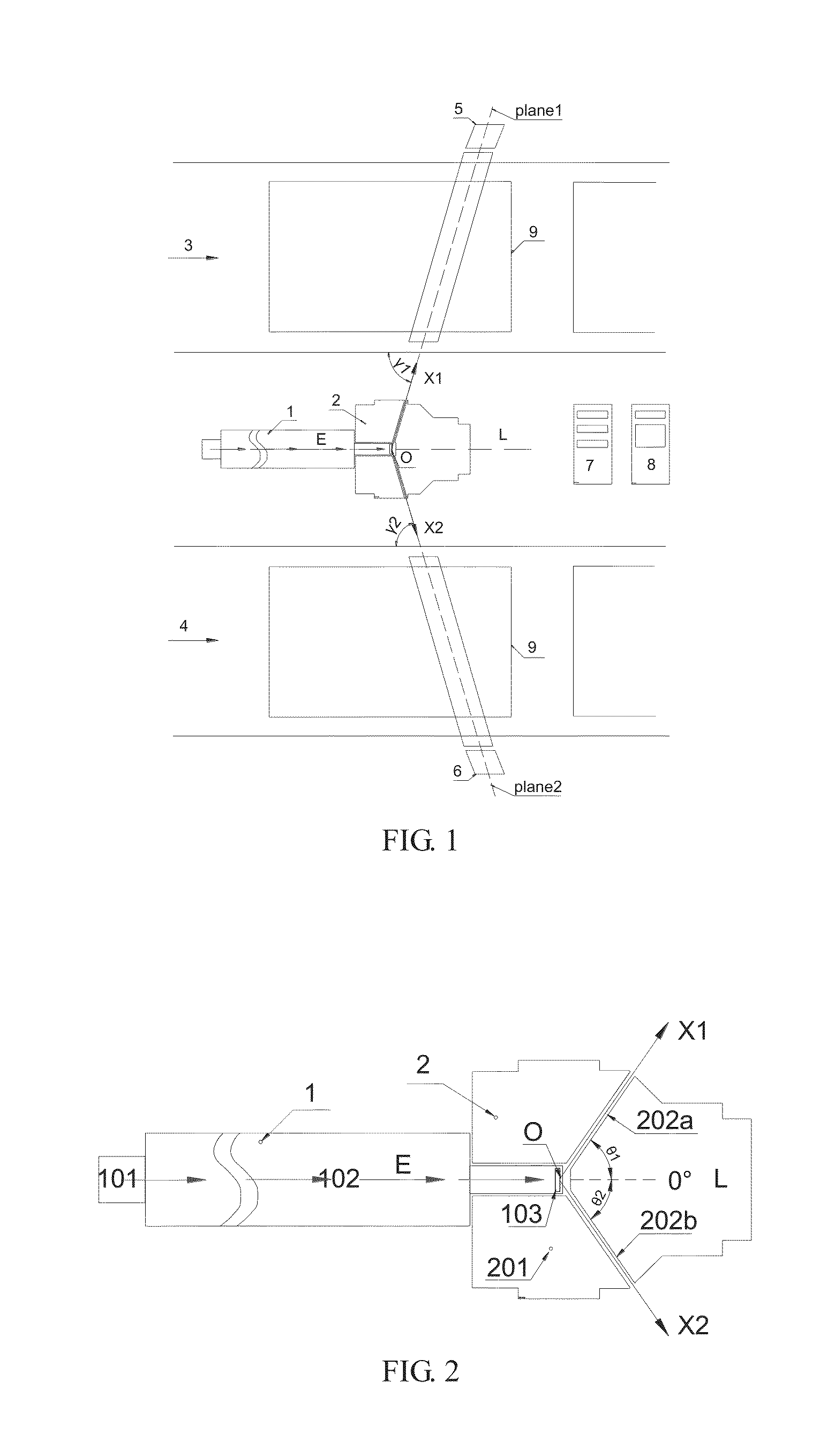
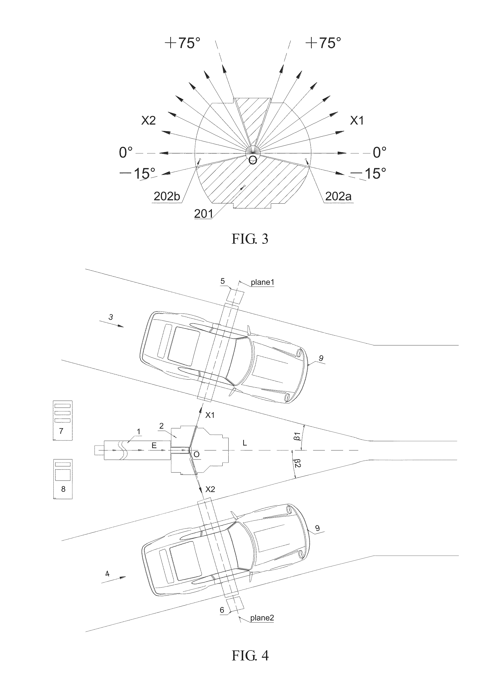
[0023]As shown in FIG. 1, FIG. 2 and FIG. 3, a dual-channel high-energy X-ray fluoroscopic imaging system comprises: an electron accelerator 1, a shielding and collimating device 2, a first inspection channel 3, a second inspection channel 4, a first detector array 5, a second detector array 6, a power supply and control subsystem 7, and a signal analysis and image processing subsystem 8. The high-energy electron accelerator 1 includes an electron emitting unit 101, an electron accelerating unit 102 and a target 103, and generates an electron beam E with energy above 2 Mev. The shielding and collimating device 2 includes a shielding structure 201 and at least two collimators 202a and 202b, and the two collimators are respectively disposed on both sides of the axis of the electron beam E. The first inspection channel 3 and the second inspection channel 4 are respectively located on both sides of the electron accelerator 1. The first collimator 202a, the first detector array 5 and the...


PUM


Abstract

The present invention may perform fluoroscopic imaging simultaneously on the subjects in at least two channels using only one electron accelerator, at least two sets of X-ray beams and at least two sets of detector systems, through the design of the electron accelerator, the shielding and collimating device, the at least two detector arrays and various mechanical composite structures. The X-ray fluoroscopic imaging system according to the present invention may be designed in specific forms of a stationary type, an assembled type, a track mobile type or vehicular mobile type, etc., and has advantages such as simple structure, low cost, strong function, good image quality and the like.

Description

[0001]This application claims priority to Chinese Patent Application No. 201310741677.6, filed with the Chinese Patent Office on Dec. 30, 2013, which is incorporated herein by reference in its entirety.FIELD OF THE INVENTION[0002]The present invention relates to a system for performing fluoroscopic imaging with high-energy X-ray generated by a high-energy electron accelerator in nondestructive inspection, fluoroscopic imaging, and a security inspection apparatus for large container inspection, vehicle inspection, air freight inspection, train inspection and the like, and in particularly, to a system for performing fluoroscopic imaging simultaneously on subjects in at least two channels by using a high-energy X-ray source.BACKGROUND OF THE INVENTION[0003]X-ray is widely applicable in the field of industrial nondestructive detection, security inspection and the like. For a large-sized subject to be detected, such as a boiler, a airspace engine, a bulk cargo at the airport / railway / cust...

Claims


Application Information

Patent Timeline
Patent Type & Authority Applications(United States)
IPC IPC(8): G01V5/00
CPCG01V5/0066G01V5/0016G01V5/223G01V5/226G01V5/22G01V5/232
Inventor TANG, HUAPINGCHEN, ZHIQIANGTANG, CHUANXIANGCHEN, HUAIBILI, YUANJINGZHAO, ZIRANLIU, YAOHONGSUN, SHANGMINYAN, XINSHUIQIN, ZHANFENG
Owner NUCTECH CO LTD
Learn More