Method for connecting a bottom pipe and a riser pipe

Active Publication Date: 2017-03-16
TECH FRANCE SA
View PDF2 Cites 2 Cited by
  • Summary
  • Abstract
  • Description
  • Claims
  • Application Information

AI Technical Summary

Benefits of technology

[0008]One problem that arises and that the present invention seeks to solve is therefore that of proposing a connection

Problems solved by technology

Hydrocarbons are extracted from increasingly deep sea beds, on the one hand, and the underwater operating facilities are complex and require the use of a plurality of flow-line pipes and risers, on the other.
The difficulties lie in installing these underwater pipes from the surface.
In particular, through this dense array of pipes it is awkward to connect a flow-line pipe with a riser.
Thus, the facility described in document EP 1 395 731 B, whereby the riser and the flow-line pipe

Method used


Image

  • Method for connecting a bottom pipe and a riser pipe
  • Method for connecting a bottom pipe and a riser pipe
  • Method for connecting a bottom pipe and a riser pipe

Examples


Example

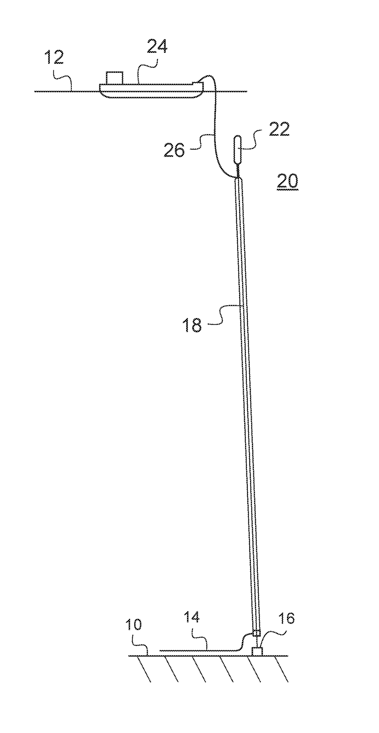
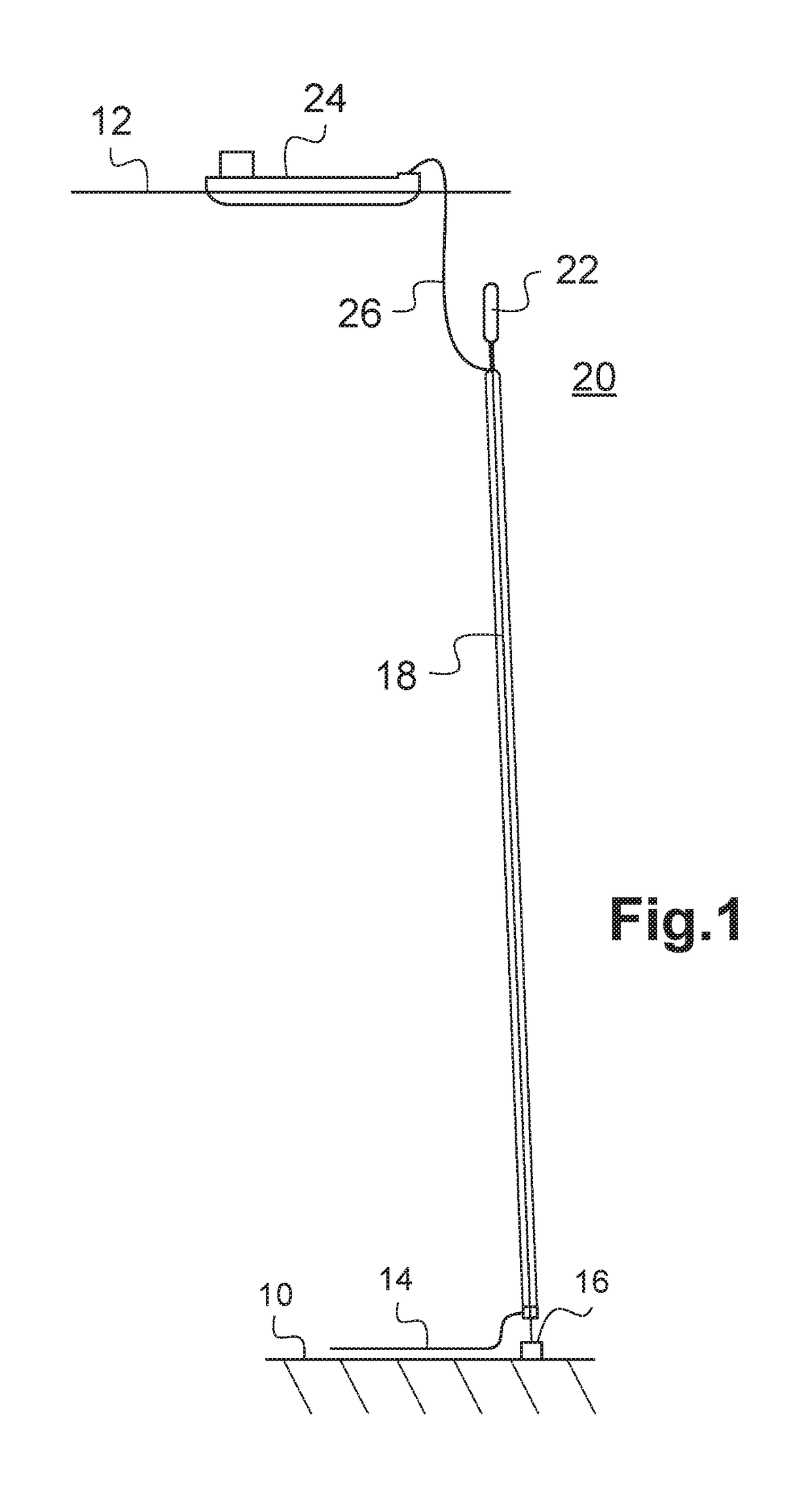
[0031]FIG. 1 schematically illustrates a head of water, for example of 1500 m between the sea bed 10 and a surface 12. A bottom underwater pipe or flow-line pipe 14 extends along the sea bed 10. It arrives at an anchoring zone 16 and may come directly from an underwater facility, not depicted, or alternatively from a well capable of delivering a hydrocarbon. From the anchor zone 16 and toward the surface 12 there extends, substantially vertically, an underwater riser 18 extending as far as a subsurface zone 20 situated below the surface 12 and in which it is held by a float 22. Vertically above this and at the surface 12 there floats a surface vessel 24 connected to the underwater riser 18 by means of a flexible pipe 26. In that way, hydrocarbon flowing along inside the underwater flow-line pipe 14 may be conveyed as far as the surface vessel 24 via the underwater riser 18 and the flexible pipe 26.

[0032]Just one underwater flow-line pipe 14 is depicted in FIG. 1 and this is connecte...


PUM


Abstract

A facility and a method for connecting a bottom submarine pipe (14) and a riser submarine pipe. The riser submarine pipe has an upstream end (62) with a fitting (66) on the end thereof, while the bottom submarine pipe (14) has a downstream end (46) provided with a connecting end piece (50). The method includes the following steps: a) an anchoring support (38) is supplied; b) the upstream end (62) and the downstream end (46) are held, while the fitting (66) extends facing the connecting end piece (50); and c) the fitting (66) and the connecting end piece (50) are brought towards each other for connection. The fitting (66) of the upstream end (62) is held still in relation to the anchoring support (38), and the connecting end piece (50) is moved towards the fitting (66).

Description

CROSS-REFERENCE TO RELATED APPLICATIONS[0001]The present application is a 35 U.S.C. §§371 national phase conversion of PCT / FR2015 / 051183, filed_May 4, 2015, which claims priority of French Patent Application No. 1454131, filed May 7, 2014, the contents of which are incorporated by reference herein. The PCT International Application was published in the French language.TECHNICAL FIELD[0002]The present invention relates to a method for connecting an underwater pipe stretched out on a sea bed and an underwater riser, and to a facility for implementing the method.[0003]One envisioned field of application is that of the transportation of hydrocarbons in an offshore environment.BACKGROUND OF THE INVENTION[0004]Known facilities comprise a bottom pipe more commonly known as a flow-line pipe, and an underwater riser pipe, often also referred to as a riser, for conveying the hydrocarbon from the sea bed where it leaves the flow-line pipe to the surface situated vertically above the sea bed.[0...

Claims


Application Information

Patent Timeline
IPC IPC(8): F16L1/26F16L1/15E21B43/01
CPCF16L1/26F16L1/15E21B43/0107E21B17/085
Inventor LUPPI, ANGEMADASCHI, CEDRIC
Owner TECH FRANCE SA
Why Eureka
Try Eureka