Physical quantity sensor, sensor device, electronic apparatus, and moving object

a technology of physical quantity and sensor device, applied in the direction of speed measurement using gyroscopic effects, instruments, surveying and navigation, etc., can solve the problems of detection accuracy degradation, and achieve the effect of excellent detection accuracy

Active Publication Date: 2017-03-16
SEIKO EPSON CORP
View PDF2 Cites 9 Cited by
  • Summary
  • Abstract
  • Description
  • Claims
  • Application Information

AI Technical Summary

Benefits of technology

[0007]An advantage of some aspects of the invention is to provide a physical quantity sensor that can improve detection accuracy and to provide a sensor device, an electronic apparatus, and a moving object that include the physical quantity sensor.

Problems solved by technology

As a result, there has been a problem in that the detection accuracy deteriorates.

Method used


Image

  • Physical quantity sensor, sensor device, electronic apparatus, and moving object
  • Physical quantity sensor, sensor device, electronic apparatus, and moving object
  • Physical quantity sensor, sensor device, electronic apparatus, and moving object

Examples


first embodiment

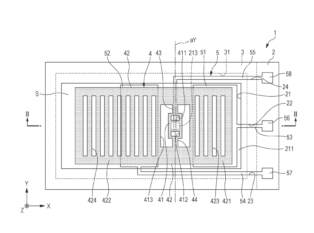
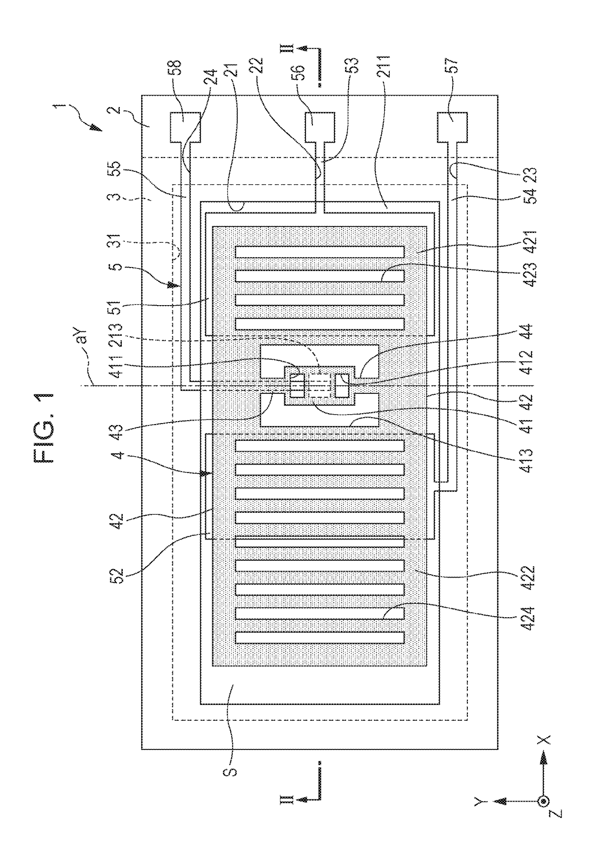
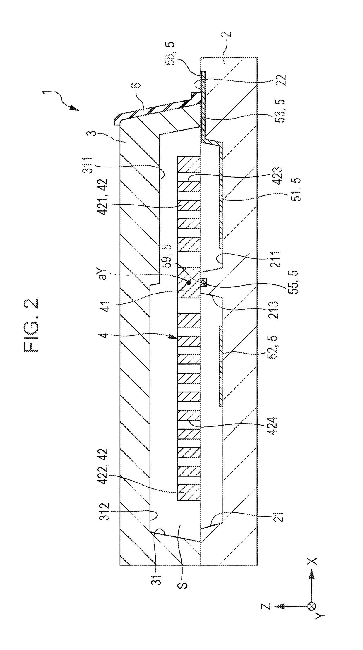
[0044]FIG. 1 is a plan view (top view) illustrating a physical quantity sensor in a first embodiment of the invention. FIG. 2 is a cross-sectional view taken along the line II-II in FIG. 1. In each of the figures, for the convenience of the description, X axis, Y axis, and Z axis are illustrated as three mutually perpendicular axes. A distal end side of an arrow indicating each axis is assumed to be “+” and a base end side of the arrow is assumed to be “−”. In addition, hereinafter, a direction parallel to the X axis is referred to as an “X axis direction”, a direction parallel to the Y axis is referred to as a “Y axis direction”, and a direction parallel to the Z axis is referred to as a “Z axis direction”. In addition, the +Z axis direction side is referred to as “upper side” and the −Z axis direction side is referred to as “lower side”.

[0045]A physical quantity sensor 1 illustrated in FIG. 1 and FIG. 2 is used as, for example, an inertial sensor, and specifically is used as an ac...

second embodiment

[0077]Next, a second embodiment of the invention will be described.

[0078]FIG. 5 is a plan view (top view) illustrating a physical quantity sensor in the second embodiment of the invention. FIG. 6 is a schematic diagram for describing a first region and a second region in the physical quantity sensor illustrated FIG. 5.

[0079]The present embodiment is similar to the first embodiment except that the shapes of the first electrode and the second electrode in a plan view in the present embodiment are different from each other.

[0080]The description hereafter relates to the second embodiment and the description will be focused on the points different from that in the embodiment described above, and the descriptions for points similar to that in the embodiment described above will be omitted.

[0081]A physical quantity sensor 1A illustrated in FIG. 5 includes a first fixed electrode 51A (a first electrode) and a second fixed electrode 52A (a second electrode) which are disposed on an inner sid...


PUM


Abstract

A physical quantity sensor includes a base substrate, a movable portion that is oscillatably provided around an axis while facing the base substrate and that is divided into a first movable portion and a second movable portion, a first fixed electrode that is disposed on the base substrate facing the first movable portion, and a second fixed electrode that is disposed on the base substrate facing the second movable portion. The first fixed electrode and the second fixed electrode are configured so as to offset at least a part of a difference between a first fringe capacitance, which is between the first movable portion and the first fixed electrode, and a second fringe capacitance, which is between the second movable portion and the second fixed electrode.

Description

BACKGROUND[0001]1. Technical Field[0002]The present invention relates to a physical quantity sensor, a sensor device, an electronic apparatus, and a moving object.[0003]2. Related Art[0004]As a physical quantity sensor that detects a physical quantity such as acceleration or an angular velocity, a so-called seesaw type sensor is known (for example, refer to JP-A-2013-040856). For example, the physical quantity sensor disclosed in JP-A-2013-040856 includes a base substrate, a sensor portion which is oscillatably supported by the base substrate and on which a movable electrode portion is provided via the center of oscillation axis on each of one side and the other side, and a fixed electrode portion that is provided on the base substrate so as to face each movable electrode portion. In such a physical quantity sensor, it is possible to detect a physical quantity such as acceleration or an angular velocity based on an electrostatic capacitance between the movable electrode portion and ...

Claims


Application Information

Patent Timeline
Patent Type & Authority Applications(United States)
IPC IPC(8): G01C19/5755G01C19/5769
CPCG01C19/5769G01C19/5755G01D5/24G01P3/44G01P15/125G01P2015/0831G01P2015/0874G01P2015/0837
Inventor TANAKA, SATORU
Owner SEIKO EPSON CORP
Why Eureka
Try Eureka