Supercharge Your Innovation With Domain-Expert AI Agents!

System and method for reducing power consumption in a power supply circuit

a power supply circuit and power supply technology, applied in the direction of transformers, electric variable regulation, instruments, etc., can solve the problems of minor interruption of supply voltage, overload conditions in electrical devices, and high cost of all these technologies, and achieve the effect of convenient commercial choi

Inactive Publication Date: 2017-03-16
ECRTECH HLDG
View PDF4 Cites 1 Cited by
  • Summary
  • Abstract
  • Description
  • Claims
  • Application Information

AI Technical Summary

Benefits of technology

The system effectively reduces power consumption by adjusting the output voltage within predetermined limits, minimizing performance impact on devices, reducing environmental strain, and lowering costs compared to traditional solutions, while maintaining high current carrying capacity and stability.

Problems solved by technology

However all of these technologies are expensive and create a minor interruption in the supply voltage as a result of their break-before-make technology.
If the supply voltage is interrupted in this fashion, overload conditions may occur in the electrical device.
Auto-transformers, being fixed-ratio, non-isolating transformers, in their generic design are not capable of ensuring a fixed range of voltage output in an environment with fluctuating input voltage.
Therefore, E and I auto-transformers are not ultimately suitable for widespread applications in energy reduction solutions.
Clearly any voltage below 205V is inappropriate for use in normal mains power, as an under voltage scenario may occur and risk damage to equipment.
Variacs may be useful in laboratory testing for example, however are an impractical and prohibitively expensive solution for some other applications which require only an isolated range of voltage.
In addition, variacs that are rated for use at 50 amps for example are extremely heavy and are typically oil cooled.
However, this circuit will not be able to handle large currents when controlling the voltage to a home of factory for example.

Method used


Image

  • System and method for reducing power consumption in a power supply circuit
  • System and method for reducing power consumption in a power supply circuit
  • System and method for reducing power consumption in a power supply circuit

Examples


Embodiment Construction

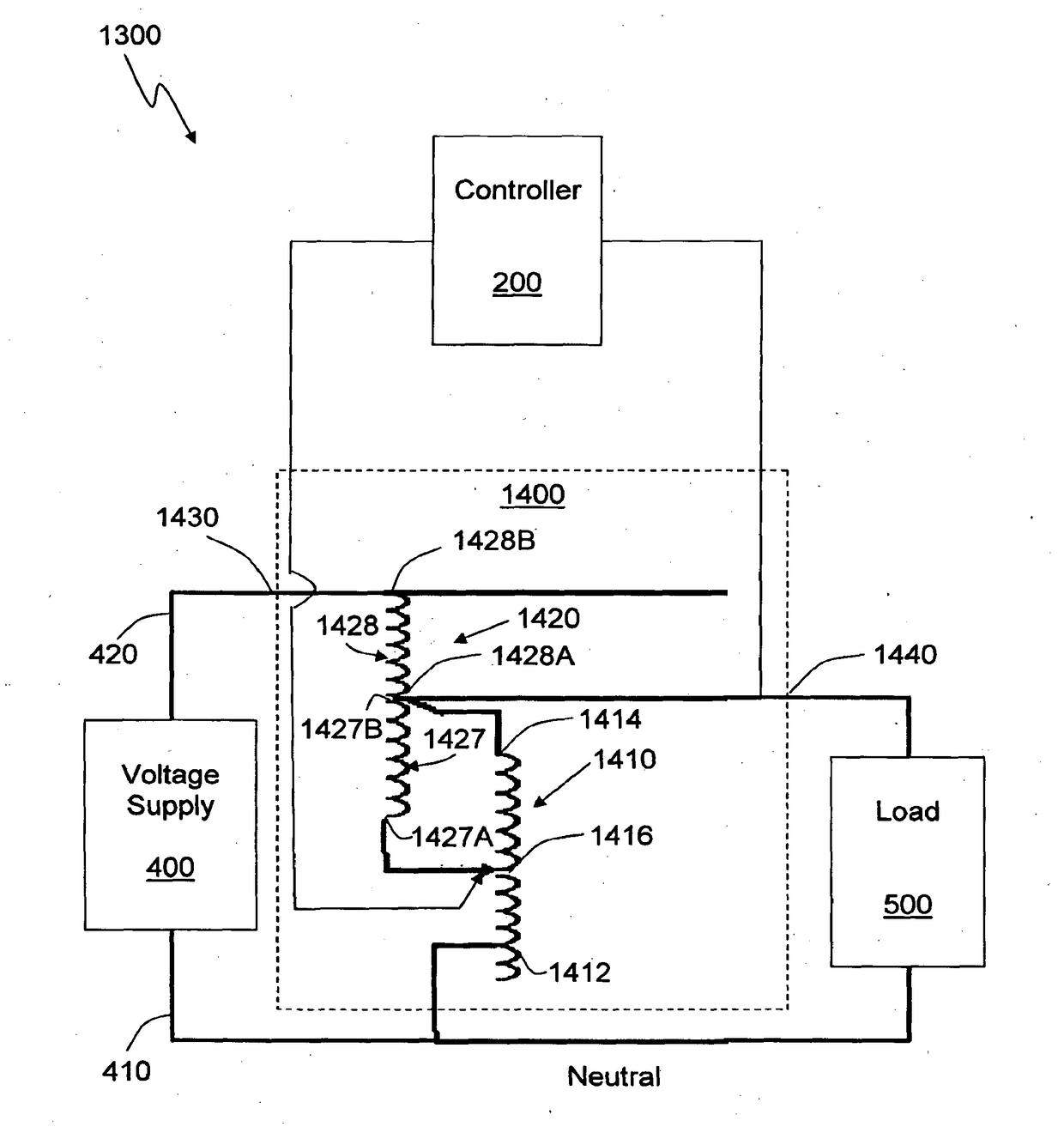
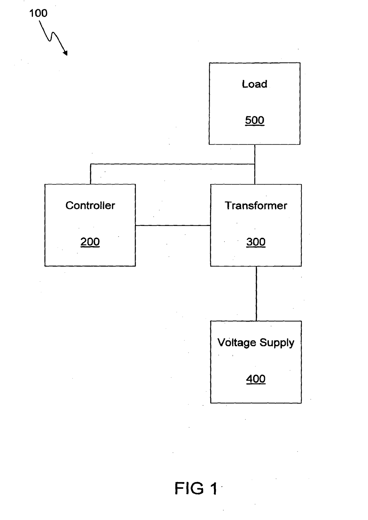
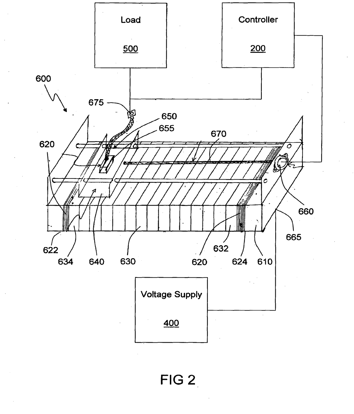
[0089]Elements of the invention are illustrated in concise outline form in the drawings, showing only those specific details that are necessary to understanding the embodiments of the present invention, but so as not to clutter the disclosure with excessive detail that will be obvious to those of ordinary skill in the art in light of the present description.

[0090]In this patent specification, adjectives such as first and second, left and right, front and back, top and bottom, etc., are used solely to define one element from another element without necessarily requiring a specific relative position or sequence that is described by the adjectives. Words such as “comprises” or “includes” are not used to define an exclusive set of elements or method steps. Rather, such words merely define a minimum set of elements or method steps included in a particular embodiment of the present invention. It will be appreciated that the invention may be implemented in a variety of ways, and that this ...


PUM


Abstract

A system for reducing power consumption in a power supply circuit including: a transformer including: a core; a first winding including a first end and a second end of a first wire wound on the core; a second winding including a first end and a second end of a second wire, wherein the second wire has a larger cross-section than the first wire and the second end of the first wire is connected to the first end of the second wire; an input electrically connecting the first and second windings to the power supply circuit; and an output for connecting to a load; and a controller connected to the transformer for controlling an output voltage at the output, wherein the output voltage is less than a supply voltage at the input, to reduce the power consumption of the load.

Description

CROSS-REFERENCE TO RELATED PATENT APPLICATIONS[0001]The present application is a continuation of U.S. patent application Ser. No. 14 / 127,836, filed Jul. 30, 2014, which is a U.S. national stage application under 35 U.S.C. §371 of PCT Application No. PCT / AU2012 / 000780, filed Jun. 29, 2012, which claims priority to Australian patent application no. 2011902560, filed Jun. 29, 2011, and Australian patent application no. 2011904992, filed Nov. 30, 2011, the entireties of which are incorporated herein by reference.FIELD OF THE INVENTION[0002]This invention relates generally to a system and method for reducing power consumption in a power supply circuit, and in particular for substantially adjusting a supply voltage, and consequently supply power, relative to an internal load and an external voltageBACKGROUND OF THE INVENTION[0003]Reducing the amount of electrical power consumed by electrical devices is becoming increasingly important, not only for cost considerations, but also due to envi...

Claims


Application Information

Patent Timeline
Patent Type & Authority Applications(United States)
IPC IPC(8): G05F1/253
CPCG05F1/253G05F1/24H01F29/02H02M5/12Y02B70/00
Inventor CAMPEANU, RONGONANO, LAURENCE
Owner ECRTECH HLDG
Features
  • R&D
  • Intellectual Property
  • Life Sciences
  • Materials
  • Tech Scout
  • Unparalleled Data Quality
  • Higher Quality Content
  • 60% Fewer Hallucinations
Learn More