Control Method for Zero Voltage Switching Buck-Boost Power Converters

a control method and converter technology, applied in the direction of electric variable regulation, process and machine control, instruments, etc., to achieve the effect of improving the efficiency of the buck-boost converter

Active Publication Date: 2017-03-16
HUAWEI DIGITAL POWER TECH CO LTD
View PDF5 Cites 8 Cited by
  • Summary
  • Abstract
  • Description
  • Claims
  • Application Information

AI Technical Summary

Benefits of technology

[0010]An advantage of a preferred embodiment of the present invention is the efficiency of a buck-boost converter may be improved by zero voltage switching of the power switches of the buck-boost converter.

Problems solved by technology

On the other hand, when the battery is depleted, it may supply a voltage lower than the output voltage of the converter.

Method used


Image

  • Control Method for Zero Voltage Switching Buck-Boost Power Converters
  • Control Method for Zero Voltage Switching Buck-Boost Power Converters
  • Control Method for Zero Voltage Switching Buck-Boost Power Converters

Examples


Embodiment Construction

[0022]The making and using of the presently preferred embodiments are discussed in detail below. It should be appreciated, however, that the present invention provides many applicable inventive concepts that can be embodied in a wide variety of specific contexts. The specific embodiments discussed are merely illustrative of specific ways to make and use the invention, and do not limit the scope of the invention.

[0023]The present invention will be described with respect to preferred embodiments in a specific context, namely control methods for a high efficiency buck-boost converter. Hereinafter, various embodiments will be explained in detail with reference to the accompanying drawings.

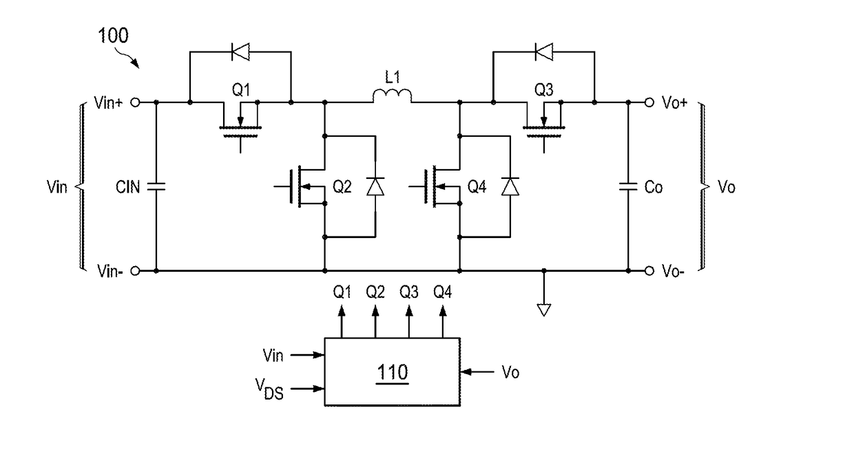
[0024]FIG. 1 illustrates a schematic diagram of a buck-boost converter in accordance with various embodiments of the present disclosure. The buck-boost converter 100 comprises a first high-side switch Q1, a first low-side switch Q2, a second high-side switch Q3, a second low-side switch Q4 and an induc...


PUM


Abstract

A method comprises providing a buck-boost converter comprising a first high-side switch and a first low-side switch connected in series across an input capacitor, a second high-side switch and a second low-side switch connected in series across an output capacitor and an inductor coupled between a common node of the first high-side switch and the first low-side switch, and a common node of the second high-side switch and the second low-side switch, detecting a first voltage resonance waveform across a switch of the buck-boost converter and turning on the switch of the buck-boost converter when the first voltage resonance waveform falls to zero.

Description

TECHNICAL FIELD[0001]The present invention relates to a power converter, and, in particular embodiments, to control mechanisms for buck-boost converters.BACKGROUND[0002]A power converter transforms an input voltage into a regulated output voltage and supplies a current required by an external load such as integrated circuits and the like. Depending on whether a transformer is incorporated into a power converter, switching power converters can be divided into two categories, namely isolated power converters and non-isolated power converters. Isolated power converters can be implemented by using different power topologies, such as flyback converters, forward converters, half bridge converters, full bridge converters, push-pull converters, inductor-inductor-capacitor (LLC) resonant converters and the like. Likewise, non-isolated power converters can be implemented by using different power topologies such as buck converters, boost converters, buck-boost converters, linear regulators, an...

Claims


Application Information

Patent Timeline
Patent Type & Authority Applications(United States)
IPC IPC(8): H02M3/158
CPCH02M3/1582H02M1/0058Y02B70/10
Inventor FU, DIANBOHUANG, JINBOLIU, CEYE, LIMINGDAI, HEPINGCHEN, DAOSHEN
Owner HUAWEI DIGITAL POWER TECH CO LTD
Why Eureka
Try Eureka