Primary Side Controlled LED Driver with Ripple Cancellation

a technology of ripple cancellation and led driver, which is applied in the direction of efficient power electronics conversion, electric lighting sources, and electric light sources, etc., can solve the problems of ripple in the output voltage at harmonics of line frequency, but at the expense of lower efficiency and higher component cos

Active Publication Date: 2017-03-16
QUEENS UNIV OF KINGSTON
View PDF4 Cites 4 Cited by
  • Summary
  • Abstract
  • Description
  • Claims
  • Application Information

AI Technical Summary

Benefits of technology

[0015]In some embodiments, the circuit further comprises: a first primary side sensor that senses the first AC voltage ripple and outputs a first sensor signal; a second primary side sensor that senses the second AC volt...

Problems solved by technology

However, this results in a ripple in the output voltage at harmonics of the line frequency.
A two-stage LED drive...

Method used


Image

  • Primary Side Controlled LED Driver with Ripple Cancellation
  • Primary Side Controlled LED Driver with Ripple Cancellation
  • Primary Side Controlled LED Driver with Ripple Cancellation

Examples


example 1

LED Driver

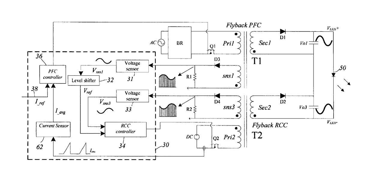
[0073]FIG. 7 shows a block diagram of an embodiment of a primary side controlled LED driver with ripple cancellation. Vo1 and Vo3 are sensed at the primary side by sns1 winding of transformer T1 and sns3 winding of transformer T2, respectively. The LED current is sensed at the primary side via the current in transformer T2. The embodiment includes two control loops. One loop regulates the LED current and includes primary side current sensor 62 to generate I_avg, a PFC controller 36 that compares I_avg and I_ref, and generates a gating signal for primary side switch Q1 of the power circuit. The second loop controls the ripple cancellation converter output Vo3, and includes a first voltage sensor 31, a second voltage sensor 33, a level shifter 32, and RCC controller 34. The RCC controller 34 compares Vsns1 and Vsn3 and generates a gating signal for the switch Q2 of the ripple cancellation converter. The primary side controller 30 is highlighted by the dashed box. From FIG. 7...

example 2

Experimental Results

[0074]A 35 W (50 V / 0.7 A) experimental LED driver was built, based on the embodiment of FIG. 7, to verify the performance of the driver. The following components were used:

Flyback PFC SectionTransformer turns ratio Npri:Nsec38:15Primary side winding inductance (Lpri)470 μHMOSFET Q1STF11NM80PFC controllerFA5601NOutput capacitor Co1470 μF, 63 VS & HHA5351IBZOpAmpTLV274Ripple Cancellation Converter SectionTransformer turn ratio Npri:Nsec 1:1Primary side winding inductance 19 μHMOSFET Q2ZXMN4A06GTARCC input capacitor Caux160 μF, 16 VRCC output capacitor Co220 μF, 16 VRCC controllerFAN6961S & HHA5351IBZLED Load SectionLED load (23 LEDs connected in series)LR W5AM-HZJZ-1-Z

[0075]In order to conduct an objective evaluation, the performance of a conventional flyback LED driver and a two-stage (flyback PFC.+Buck DC-DC) LED driver were included for comparison. The plot of FIG. 8 compares the efficiency of the three designs. The ITC circuits in three designs were identical.

[...


PUM


Abstract

Described herein are methods and circuits for improving the performance of an AC to DC power supply. The methods and circuits achieve high power factor (PF) at the AC side and at the same time, reduce or substantially eliminate ripple in the DC output power. The methods and circuits provide an isolated topology including primary side voltage and current sensing and primary side ripple cancellation control. The methods and circuits may be used in any application where high power factor and/or low output ripple are required. In particular, the methods and circuits may be used in DC lighting applications, such as in light emitting diode (LED) lighting, wherein suppression of low frequency ripple in the output power eliminates visible flickering.

Description

FIELD[0001]This invention relates to methods and circuits for improving the performance of an AC to DC power supply. In particular, methods and circuits are provided for power supplies that achieve high power factor (PF) at the AC side and at the same time, reduce or substantially eliminate ripple in the DC output power. The methods and circuits may be used in any application where high power factor and / or low output ripple are required. In particular, the methods and circuits may be used in DC lighting applications, such as in light emitting diode (LED) lighting, wherein suppression of low frequency ripple in the output power eliminates visible flickering.BACKGROUND[0002]Regulation concerning power factor correction for a wide range of devices is becoming increasingly stringent. For example, new regulation requires power factor correction for any light emitting diode (LED) power supply with output power higher than 5 W.[0003]For low to medium power level (e.g., 5 W to 100 W), a fly...

Claims


Application Information

Patent Timeline
IPC IPC(8): H05B33/08H02M1/42H02M1/14H05B44/00
CPCH05B33/0809H02M1/42H02M1/14H05B33/0845H02M1/143H02M1/4258Y02B70/10H05B45/38H05B45/10H05B45/385H05B45/375H02M1/0093
Inventor FANG, PENGLIU, YAN-FEI
Owner QUEENS UNIV OF KINGSTON
Why Eureka
Try Eureka