Methods and System for Performing 3-D Tool Tracking by Fusion of Sensor and/or Camera Derived Data During Minimally Invasive Robotic Surgery

a technology of sensor and/or camera derived data, applied in the field of minimally invasive surgery, can solve problems such as tissue damag

Active Publication Date: 2017-03-23
INTUITIVE SURGICAL OPERATIONS INC
View PDF8 Cites 60 Cited by
  • Summary
  • Abstract
  • Description
  • Claims
  • Application Information

AI Technical Summary

Benefits of technology

[0011]To make each of multiple tools easily distinguishable to the surgeon on the workstation display screen and also to patient-side staff, a number of computer assisted techniques may be employed such as: predicting the position and orientation of the tool, and overlaying a computer aided design (“CAD”) model of the tool, or other virtual mark or indicator, over the predicted position and orientation of the tool in the display screen; predicting the position and orientation of the tool, and uniquely marking each tool at its predicted position and orientation to make it distinguishable from other tools on the display screen; and predicting the position and orientation of the tool, and erasing or brushing out the shaft of the tool while highlighting its end effector in some fashion so that the end effector seemingly floats in and stands out on the display screen.
[0012]One advantage, for example, of uniquely marking each tool at its predicted position and orientation to make it distinguishable from other tools on the display screen, is that it a) makes it easier for the surgeon (who only sees the tools inside the body) to communicate with a patient-side staff (who only see the tools outside the body) about specific tools, and b) makes sure the surgeon is aware of tools that might be outside the field of view. This is especially important when there are more than two tools, since the surgeon may see only two and assume those are the two he is controlling with his two hands when in fact he is controlling (i.e. moving) another tool outside the field of view, potentially damaging tissue.

Problems solved by technology

This is especially important when there are more than two tools, since the surgeon may see only two and assume those are the two he is controlling with his two hands when in fact he is controlling (i.e. moving) another tool outside the field of view, potentially damaging tissue.

Method used


Image

  • Methods and System for Performing 3-D Tool Tracking by Fusion of Sensor and/or Camera Derived Data During Minimally Invasive Robotic Surgery
  • Methods and System for Performing 3-D Tool Tracking by Fusion of Sensor and/or Camera Derived Data During Minimally Invasive Robotic Surgery
  • Methods and System for Performing 3-D Tool Tracking by Fusion of Sensor and/or Camera Derived Data During Minimally Invasive Robotic Surgery

Examples


Embodiment Construction

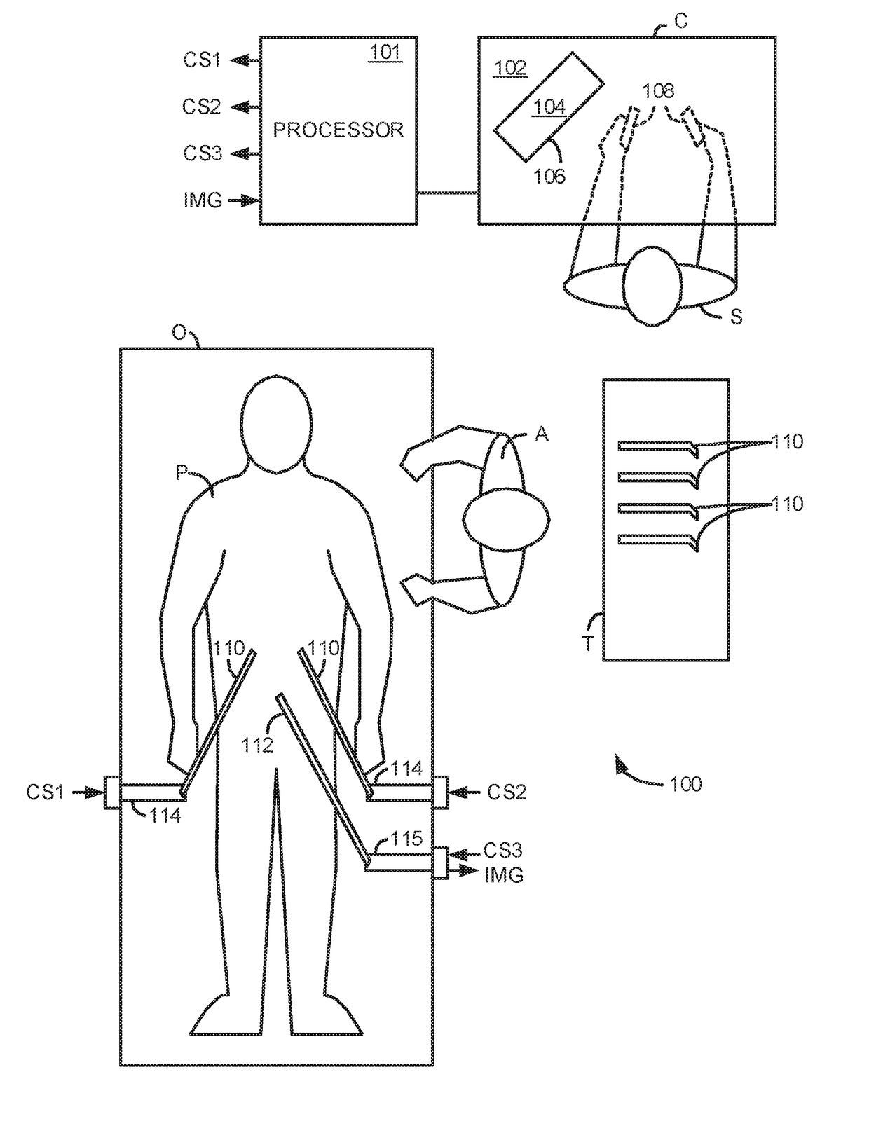
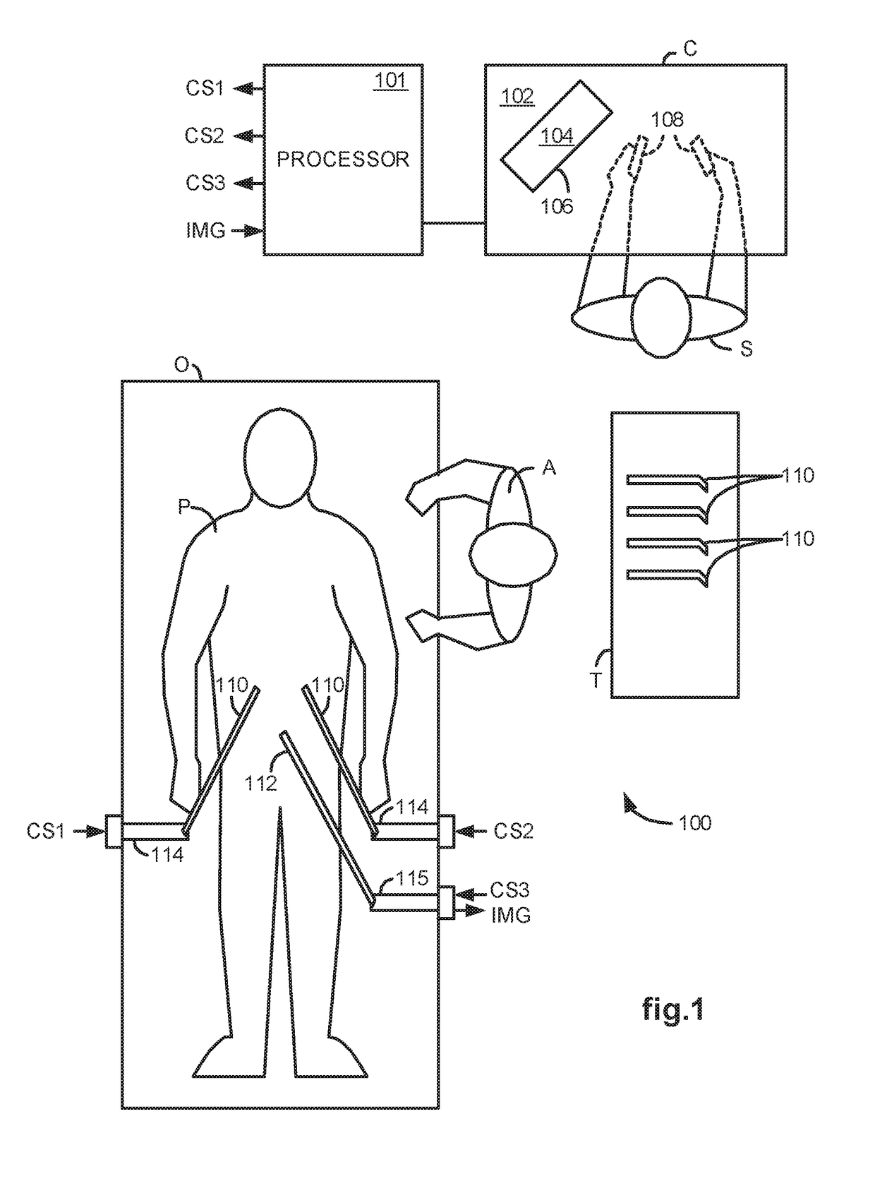
[0048]FIG. 1 illustrates, as an example, a Minimally Invasive Robotic Surgical (MIRS) system 100 including a Console (“C”) utilized by a Surgeon (“S”) while performing a minimally invasive diagnostic or surgical procedure, usually with assistance from one or more Assistants (“A”), on a Patient (“P”) who is lying down on an Operating table (“O”).

[0049]The Console includes a support 102, a monitor 104 for displaying an image of a surgical site to the Surgeon, and one or more control devices 108. The control devices 108 may include any one or more of a variety of input devices, such as joysticks, gloves, trigger-guns, hand-operated controllers, voice recognition devices or the like.

[0050]The Surgeon performs a procedure by manipulating the control devices 108 which in turn, cause robotic mechanisms 114 to manipulate their respective removably coupled instrument or tool assembly 110 (hereinafter simply referred to as a “tool”) through a minimally invasive incision in the body of the Pat...


PUM


Abstract

Methods and system perform tool tracking during minimally invasive robotic surgery. Tool states are determined using triangulation techniques or a Bayesian filter from either or both non-endoscopically derived and endoscopically derived tool state information, or from either or both non-visually derived and visually derived tool state information. The non-endoscopically derived tool state information is derived from sensor data provided either by sensors associated with a mechanism for manipulating the tool, or sensors capable of detecting identifiable signals emanating or reflecting from the tool and indicative of its position, or external cameras viewing an end of the tool extending out of the body. The endoscopically derived tool state information is derived from image data provided by an endoscope inserted in the body so as to view the tool.

Description

STATEMENT AS TO RIGHTS TO INVENTIONS MADE UNDER FEDERALLY SPONSORED RESEARCH OR DEVELOPMENT[0001]This invention was made with United States Government Support under cooperative agreement number: 70NANB1H3048 awarded by the National Institute of Standards and Technology (NISI). The United States government has certain rights in the invention.FIELD OF THE INVENTION[0002]The present invention generally relates to minimally invasive surgery and in particular, to methods and a system for performing 3-D tool tracking by fusion of sensor and / or camera derived data (e.g. tool position, velocity) during minimally invasive robotic surgery.BACKGROUND OF THE INVENTION[0003]Minimally invasive surgical techniques are aimed at reducing the amount of extraneous tissue that is damaged during diagnostic or surgical procedures, thereby reducing patient recovery time, discomfort, and deleterious side effects. As a consequence, the average length of a hospital stay for a standard surgery may be shortene...

Claims


Application Information

Patent Timeline
Patent Type & Authority Applications(United States)
IPC IPC(8): A61B34/20A61B1/00A61B34/30A61B5/06A61B1/04
CPCA61B34/20A61B5/06A61B2034/2065A61B34/30A61B1/00193A61B1/04A61B1/3132A61B5/725A61B2090/0818A61B2034/102A61B90/36A61B2090/364A61B90/361A61B34/37A61B90/39A61B5/061A61B5/062A61B1/00194
Inventor HOFFMAN, BRIAN D.LARKIN, DAVID Q.PRISCO, GIUSEPPEZHANG, GUANGHUA G.KUMAR, RAJESH
Owner INTUITIVE SURGICAL OPERATIONS INC
Why Eureka
Try Eureka