Patterned material layer and patterning method
a technology of patterned material and patterning method, which is applied in the field of patterned material layer, can solve problems such as problems, and achieve the effect of facilitating transmission
- Summary
- Abstract
- Description
- Claims
- Application Information
AI Technical Summary
Benefits of technology
Problems solved by technology
Method used
Image
Examples
first embodiment
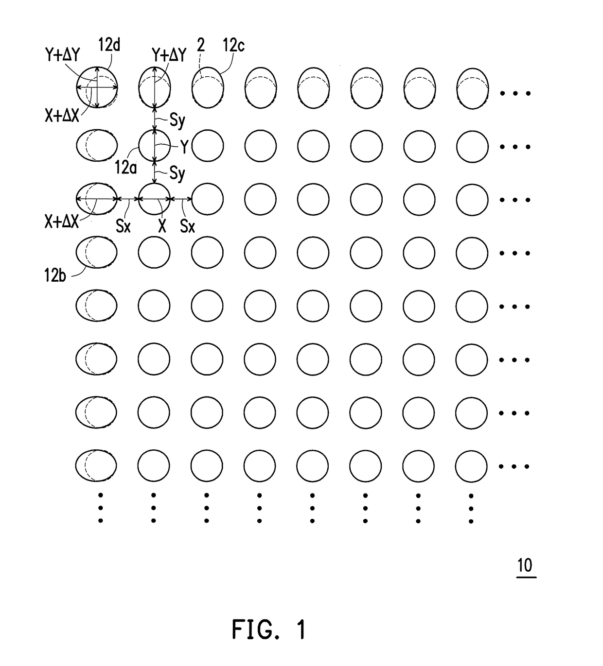
[0024]FIG. 1 illustrates a local layout of a patterned material layer according to this invention.
[0025]Referring to FIG. 1, in the layer 10 (when the separate patterns include hole patterns) or on the substrate 10 (when the separate patterns include pillar patterns), only the separate patterns 12c in the outmost row each have a larger dimension Y+ΔY in the y-direction than the separate patterns 12a in the other rows, and only the separate patterns 12b in the outmost column each have a larger dimension X+ΔX in the x-direction than the separate patterns 12a in the other columns. The separate pattern 12d in the outmost row and also in the outmost column has both the DCD / ECD modifications, i.e., the dimension Y+ΔY in the y-direction and the dimension X+ΔX in the x-direction. It is noted that the initial separate patterns 2 without the dimensional modifications are shown by dashed lines.
[0026]The spacing (Sy) between the outmost row of separate patterns 12c and the neighboring row of se...
second embodiment
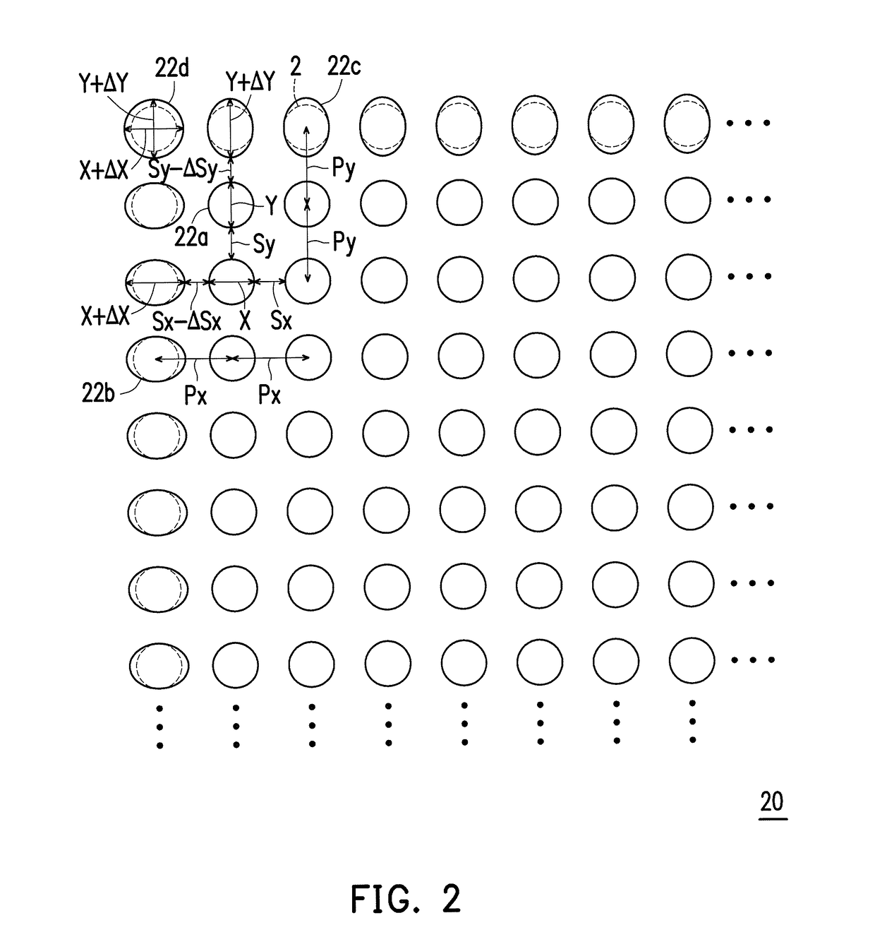
[0030]FIG. 2 illustrates a local layout of a patterned material layer according to this invention.
[0031]Referring to FIG. 2, except that the reference numerals are changed from 10, 12a, 12b, 12c and 12d to 20, 22a, 22b, 22c and 22d, the second embodiment is different from the first embodiment in that the pitch (Py) between the outmost row of separate patterns 22c and the neighboring row of separate patterns 22a among the other rows is equal to the pitch (Py) between any two of the other rows of separate patterns 22a, the pitch (Px) between the outmost column of separate patterns 22b and the neighboring column of separate patterns 22a among the other columns is equal to the pitch (Px) between any two of the other columns of separate patterns 22a, the spacing (Sy-ΔSy) between the outmost row of separate patterns 22c and the neighboring row of separate patterns 22a among the other rows is smaller than the spacing (Sy) between any two of the other rows of separate patterns 22a, and the ...
third embodiment
[0032]FIG. 3 illustrates a local layout of a patterned material layer according to this invention.
[0033]Referring to FIG. 3, except that the reference numerals are changed from 10, 12a, 12b, 12c and 12d to 30, 32a, 32b, 32c and 32d, the third embodiment is different from the first embodiment in that the spacing (Sy+ΔSy) between the outmost row of separate patterns 32c and the neighboring row of separate patterns 32a among the other rows is larger than the spacing (Sy) between any two of the other rows of separate patterns 32a, and the spacing (Sx+ΔSx) between the outmost column of separate patterns 32b and the neighboring column of separate patterns 32a among the other columns is larger than the spacing (Sx) between any two of the other columns of separate patterns 32a.
[0034]The cases where the separate patterns in more than one rows including the outmost row each have a larger dimension in the column direction and / or the separate patterns in more than one columns including the out...
PUM
 Abstract
Description
Claims
Application Information
 - R&D
- Intellectual Property
- Life Sciences
- Materials
- Tech Scout
- Unparalleled Data Quality
- Higher Quality Content
- 60% Fewer Hallucinations
Browse by: Latest US Patents, China's latest patents, Technical Efficacy Thesaurus, Application Domain, Technology Topic, Popular Technical Reports.
© 2025 PatSnap. All rights reserved.Legal|Privacy policy|Modern Slavery Act Transparency Statement|Sitemap|About US| Contact US: help@patsnap.com


