Aircraft comprising a plurality of antenna units

a technology of antenna units and aircraft, applied in the direction of antennas, antenna supports/mountings, transmission, etc., can solve the problems of time-consuming, limited, expensive, etc., and achieve the effect of reducing the amount of additional cabling required

Active Publication Date: 2017-03-23
AIRBUS DEFENCE & SPACE
View PDF4 Cites 5 Cited by
  • Summary
  • Abstract
  • Description
  • Claims
  • Application Information

AI Technical Summary

Benefits of technology

[0013]Providing a central control unit makes it possible to put the two antenna units into a second mode of operation in which multi-antenna MIMO communication is possible as a result of the two antenna units being actuated at the same time. This means that it is possible to increase the data rate at a constant band width and thus the spectral efficiency. The quality of the received signal can in turn be improved at a constant data rate, and this makes bit errors less frequent, for example. In this manner, the antenna units present in the aircraft are used therein and multi-antenna MIMO communication is made possible, without having to build additional antenna units into the aircraft.
[0018]The central control unit can be set up or configured to control the at least two antenna units in a manner corresponding to the second mode of operation when the aircraft is on the ground. Conversely, the two antenna units can be set up or configured to transmit and / or receive signals in a manner corresponding to the first mode of operation when the aircraft is in the air. Many antenna units in an aircraft, such as antenna units in a radar altimeter, an instrument landing system, a collision warning and avoidance system or a weather radar, are only required when the aircraft is in the air. Therefore, switching into the second mode of operation can improve MIMO data transmission, without this having an adverse effect on the function of the antenna units during flight.
[0021]Each communication module may comprise a software-defined radio (SDR) module. Using an SDR module means that some of the signal processing of the communication modules and / or the central control unit can be carried out using software. In this manner, the actuation of the individual antenna units can be altered in a simple and flexible manner, without having to replace corresponding hardware components. The communication modules can be arranged so as to be distributed in the aircraft in the vicinity of the respective antenna units. Alternatively, the communication modules can be arranged in a cluster in a separate region of the aircraft. The alternative mentioned last is advantageous in that the coherent clocking required for the coherent actuation of the two antenna units in the second mode of operation can be achieved by means of a short and simple SDR link. This can reduce the amount of additional cabling required in the aircraft.

Problems solved by technology

Integrating additional antenna units in aircraft is time-consuming, expensive and limited by factors such as weight, size and power consumption.

Method used


Image

  • Aircraft comprising a plurality of antenna units
  • Aircraft comprising a plurality of antenna units
  • Aircraft comprising a plurality of antenna units

Examples


first embodiment

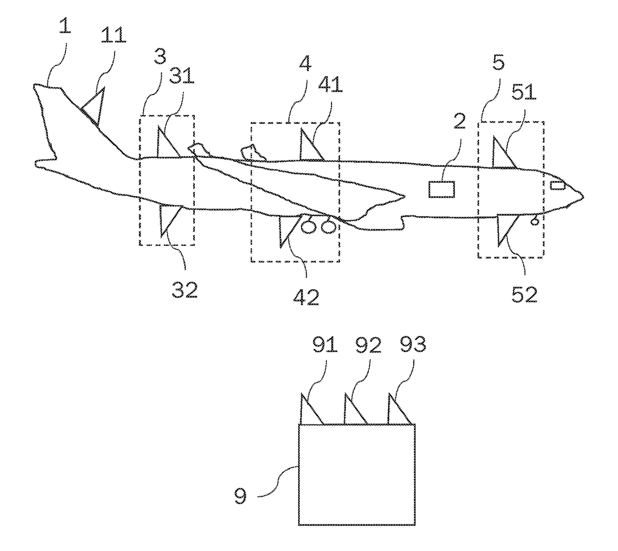
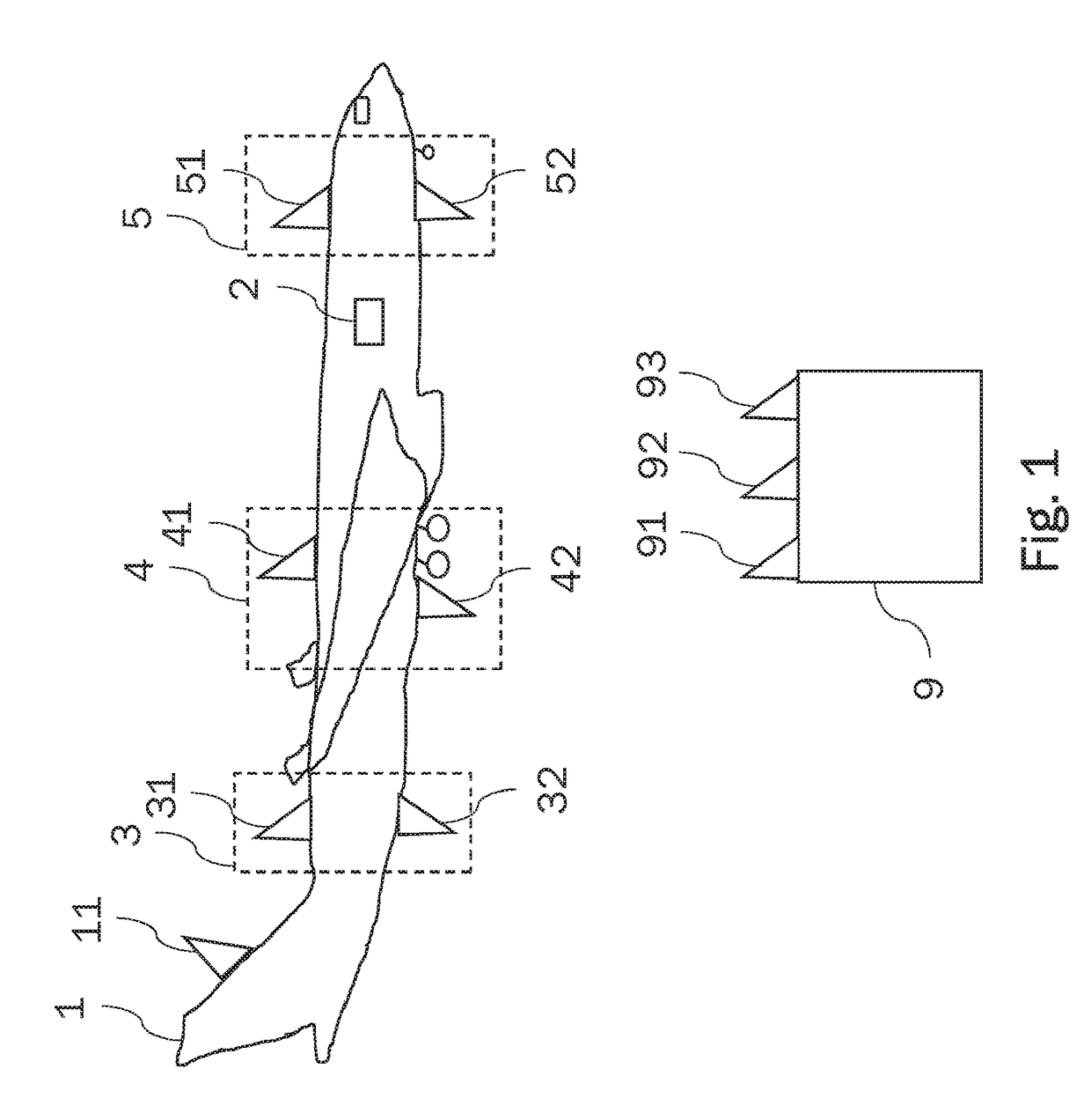
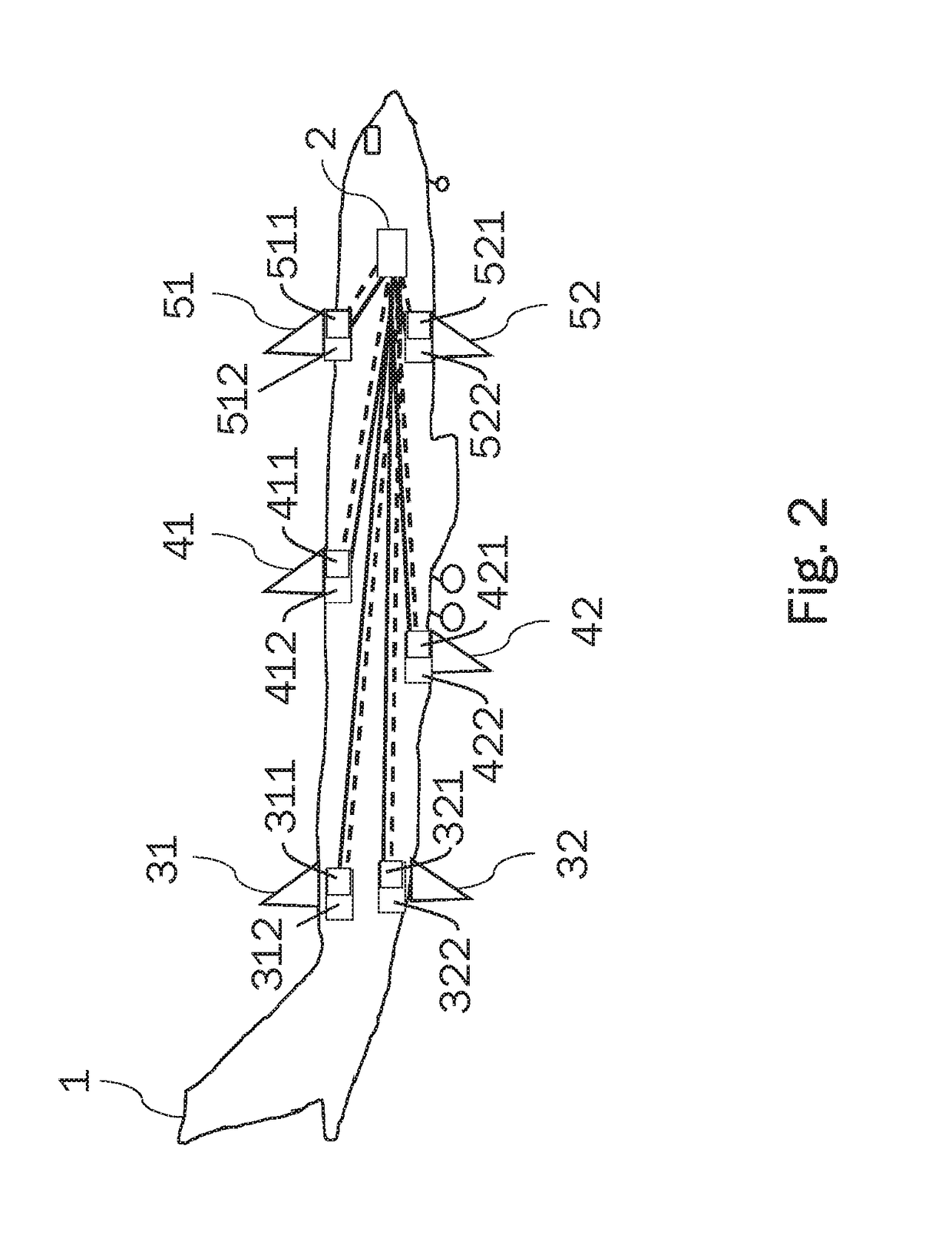
[0039]FIG. 2 and FIG. 3 show a possible first embodiment in which the central control unit 2 is electrically connected to the antenna elements 31, 32, 41, 42, 51, 52 by means of communication modules 311, 321, 411, 421, 511, 521. FIG. 3 does not show the two communication modules 511, 521 and the associated antenna elements 51, 52. The communication modules 311, 321, 411, 421, 511, 521 are connected to the control unit 2 by means of a data bus, which is indicated by continuous lines. Inter alia, the user data received or transmitted by the antenna elements 31, 32, 41, 42, 51, 52 are transmitted via the data bus. In the illustrated example, the communication modules 311, 321, 411, 421, 511, 521 are implemented by means of software-defined radio (SDR) platforms which are connected to the central control unit 2 by means of SDR links. The SDR links are indicated in FIG. 2 and FIG. 3 by dashed lines and ensure coherent clocking of the distributed SDR platforms. As shown in FIG. 2, the co...

second embodiment

[0042]The central SDR cluster 21 makes is possible to arrange the SDR platforms 311, 321, 411, 421, 511, 521 in the aircraft 1 in a compact and efficient manner The coherent links between the individual SDR platforms 311, 321, 411, 421, 511, 521 can be produced quickly and simply. In particular, in the second embodiment, there is no need for SDR links between the central control unit 2 and the SDR cluster 21, but rather only SDR links within the SDR cluster 21 are required, and this is indicated by double-headed arrows in FIG. 5.

[0043]FIG. 6 shows another possible application scenario in a helicopter. In this case, three antenna units 6, 7, 8 are actuated by means of a central control unit 2 via a central SDR cluster 21 in order to form a multi-antenna system and allow MIMO data transmission to other communication participants by means of the antenna units 6, 7, 8. In the example shown in FIG. 6, the antenna elements 6, 7, 8 are connected to the SDR cluster 21 by means of the transm...


PUM


Abstract

A flying machine or other vehicle includes at least two antenna units and a central control unit. In a first mode of operation, the two antenna units send and / or receive signals independent of each other in different, non-overlapping frequency bands. The central control unit is adapted to control the two antenna units in a second mode of operation such that the two antennas transmit and / or receive a common signal in a common frequency band using a Multiple Input Multiple Output transmission technique.

Description

CROSS-REFERENCES TO RELATED APPLICATIONS[0001]This application claims the benefit of the German patent application No. 102015218299.1 filed on Sep. 23, 2015, the entire disclosures of which are incorporated herein by way of reference.TECHNICAL FIELD[0002]This document relates to an aircraft comprising a plurality of antenna units. The disclosure relates, in particular, to aircraft comprising a plurality of antenna units which each transmit and / or receive signals, independently of one another, that are in different, non-overlapping frequency bands.BACKGROUND OF THE INVENTION[0003]A large number of antennae are conventionally built into aircraft, for example, airplanes or helicopters. These antennae are arranged at various points on the aircraft fuselage or on the airfoils and thereby perform a wide variety of functions.[0004]A first application of antennae in aircraft involves data communication. In this case, corresponding antennae make it possible to exchange speech, images or othe...

Claims


Application Information

Patent Timeline
Patent Type & Authority Applications(United States)
IPC IPC(8): H01Q1/28H01Q1/24H01Q21/00
CPCH01Q1/286H01Q1/24H01Q21/00H04B7/0689H04B7/0871H04B7/18504H04B7/18506H04B7/18508
Inventor RIETH, DOMINIKZIEGLER, VOLKERHELLER, CHRISTOPH
Owner AIRBUS DEFENCE & SPACE
Why Eureka
Try Eureka