Mobile devices charging system and method

Active Publication Date: 2017-03-23
NIPE TECH LTD
View PDF2 Cites 0 Cited by
  • Summary
  • Abstract
  • Description
  • Claims
  • Application Information

AI Technical Summary

Benefits of technology

This invention is about a device that allows for easy and intuitive control over energy transfer. It does not require physical switches or dedicated software applications and solves the problems associated with them. Additionally, the invention mentions that the user can adjust the orientation angle between the charging device and the device being charged for faster charging. This is done by using a variable DC-DC converter to increase the charging voltage.

Problems solved by technology

Mobile devices require charging over increasingly short timespans due to increased use, clock speeds, and other energy demands.
As mobile devices intend to be, as their name indicates—mobile—the ability to keep them constantly, or intermittently within short intervals, charged serves as a major challenge to mobile devices users.
Battery capacity while increasing has not experienced an increase that keeps pace with the increased energy demand of mobile devices such as cellphones, PDAs, laptops and the like.
However, these solutions are less than ideal, since the user must spend considerable amounts of money on these solutions, and must also carry around expensive and sometimes bulky and heavy gadgets in order to charge a user's battery.
Additionally, a major disadvantage of current technology is that different devices, although they may have similar input / output capacities, have different physical connections in the device.
Therefore often times, even when an individual may have access to a charger, it may deliver the correct energy input, but may be physically unable to connect to the device.
This limit is the inability of the device to output energy from the port from which it receives energy.
This means that said devices may be charged but cannot export energy to charge them.
Another drawback of existing devices involves their need for external control means to initiate and control the transfer of energy between devices.
Even if there are various devices for energy transfer between mobile devices that do not involve the use of such an application or physical switch, such devices may offer only a limited functionality, wherein energy flows only in one direction—from a mobile device with higher potential energy to the lower energy mobile device.
Although a mobile application running on one of the mobile devices provides for an effective way for users to monitor and control the rate, level, and duration of energy transfer, the need to install and run an application on a mobile device, complicates operation methods for the user that is often reluctant to install a new application on his mobile device.
Moreover, running a mobile application before every use of the energy transfer device, complicates and hinders the functionality to the user.
Such extreme measures often create severe compatibility problems with mobile devices of different manufacturers.
On the other hand, energy transfer devices with typical simple physical switches offer only limited functionality allowing the user often only to control the direction of energy flow.
Using such physical external switch components reduces the device's life span increasing the risk of breaking the device.
An additional shortcoming of such devices is that when in transit or otherwise not in the vicinity of charging sources such as wall voltage, storage batteries, or charged mobile devices, there is generally no option for energy harvesting from the surroundings.

Method used


Image

  • Mobile devices charging system and method
  • Mobile devices charging system and method
  • Mobile devices charging system and method

Examples


Embodiment Construction

[0034]The present invention will be understood from the following detailed description of preferred embodiments, which are meant to be descriptive and not limiting. For the sake of brevity, some well-known features, methods, systems, procedures, components, circuits, and so on, are not described in detail.

[0035]The term ‘mobile device’ hereinafter refers to any portable device having Turing-equivalent capability including smartphones, cellphones, PDAs, tablets, phablets, laptop computers, wearable computers, smart watches, smart glasses, and the like.

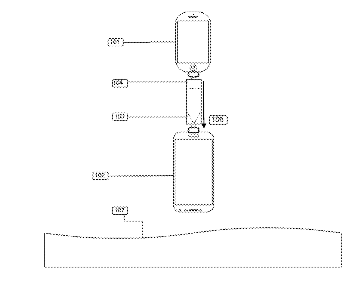
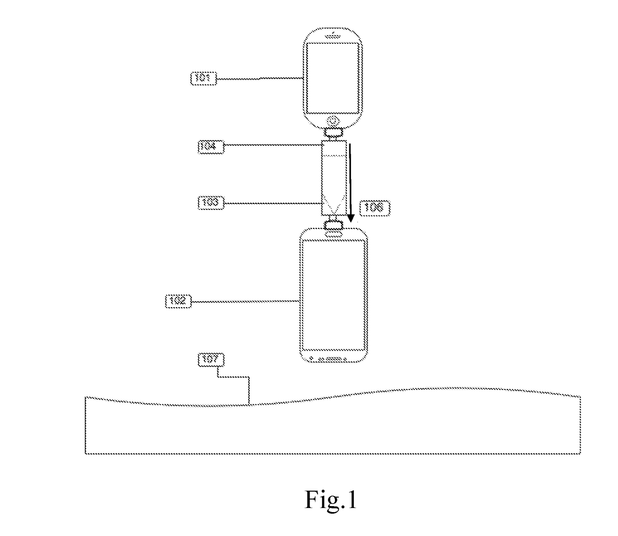
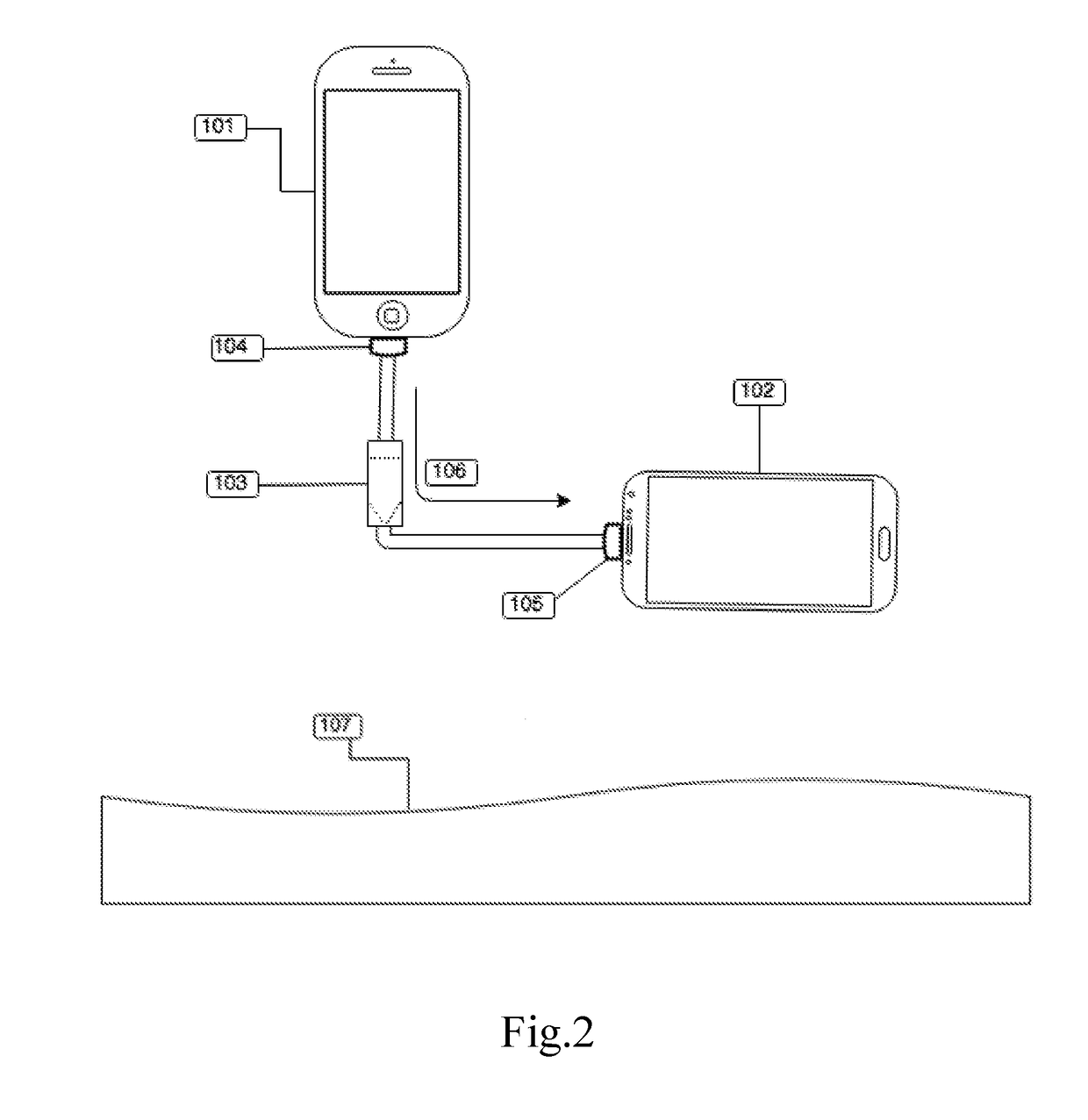
[0036]The invention comprises systems and methods for transferring energy between mobile devices such as smartphones. A number of different embodiments are provided allowing for different transfer schemes.

[0037]Power in general may be transferred from a power line in the cable such as 3.3V or 5V line of the USB2 cable or any other protocol or connection, which as the reader will doubtless recall comprises the aforementioned 3.3V or 5V l...


PUM


Abstract

The invention comprises systems and methods for transferring energy between mobile 370 devices such as smartphones comprising: energy transfer means; at least one accelerometer; a micro-controller with predefined instructions, is adapted to control charging parameters; a DC-DC converter; wherein, said accelerometer readings are processed and fed into said microcontroller for controlling said charging parameters using said predefined instructions; further wherein, control over said charge parameters is 375 achieved by changing the position of at least one of the mobile devices. A number of different embodiments are provided allowing for different transfer schemes.

Description

FIELD OF THE INVENTION[0001]The present invention relates to the field of energy transfer between mobile devices.BACKGROUND OF THE INVENTION[0002]Mobile devices require charging over increasingly short timespans due to increased use, clock speeds, and other energy demands. As mobile devices intend to be, as their name indicates—mobile—the ability to keep them constantly, or intermittently within short intervals, charged serves as a major challenge to mobile devices users. Battery capacity while increasing has not experienced an increase that keeps pace with the increased energy demand of mobile devices such as cellphones, PDAs, laptops and the like.[0003]Many solutions have been invented to attempt to deal with this problem. Some of these inventions include external battery packs which, when connected to a mobile device are able to give it an energy boost. Additionally, as in the case of certain cellular phones and laptops, an additional battery may be purchased for the device and c...

Claims


Application Information

Patent Timeline
IPC IPC(8): H02J7/00G01P15/00H04B1/3883
CPCH02J7/0044G01P15/00H04B1/3883H04M19/08
Inventor YIRMIAHU, RON
Owner NIPE TECH LTD
Why Eureka
Try Eureka